Turbojet Pylon for Aircraft

a technology for aircraft and pylons, which is applied in the direction of power plant construction, aircraft power plants, transportation and packaging, etc., can solve the problems of drag loss, turbojet efficiency and fuel consumption, and achieve the effects of reducing efficiency loss, reducing friction, and reducing bending

Inactive Publication Date: 2007-09-06
AIRBUS OPERATIONS (SAS)
View PDF2 Cites 18 Cited by
  • Summary
  • Abstract
  • Description
  • Claims
  • Application Information

AI Technical Summary

Benefits of technology

[0024] Thus, this particular arrangement of engine fasteners on the rigid structure of the pylon is capable of inducing a considerable reduction in the bending encountered at the central casing, regardless of whether this bending is due to thrusts generated by the turbojet, or due to gusts that may be encountered during the various flight phases of the aircraft.
[0025] Consequently, the above mentioned reduction in bending generates a significant reduction in friction between rotating compressor and turbine blades and the engine central casing, and therefore significantly reduces losses of efficiency due to wear of these blades.
[0026] Furthermore, the fact that engine fasteners are provided on the plurality of arcs makes it possible to significantly separate them from each other, for example the resulting s...

Problems solved by technology

Thus, in this specific case in which the large box shaped mounting pylon is arranged close to the central casing of the turbojet, this pylon inevitably creates strong disturbances-of the secondary flow escaping from the annular fan duct...

Method used


Image

  • Turbojet Pylon for Aircraft
  • Turbojet Pylon for Aircraft
  • Turbojet Pylon for Aircraft

Examples


Embodiment Construction

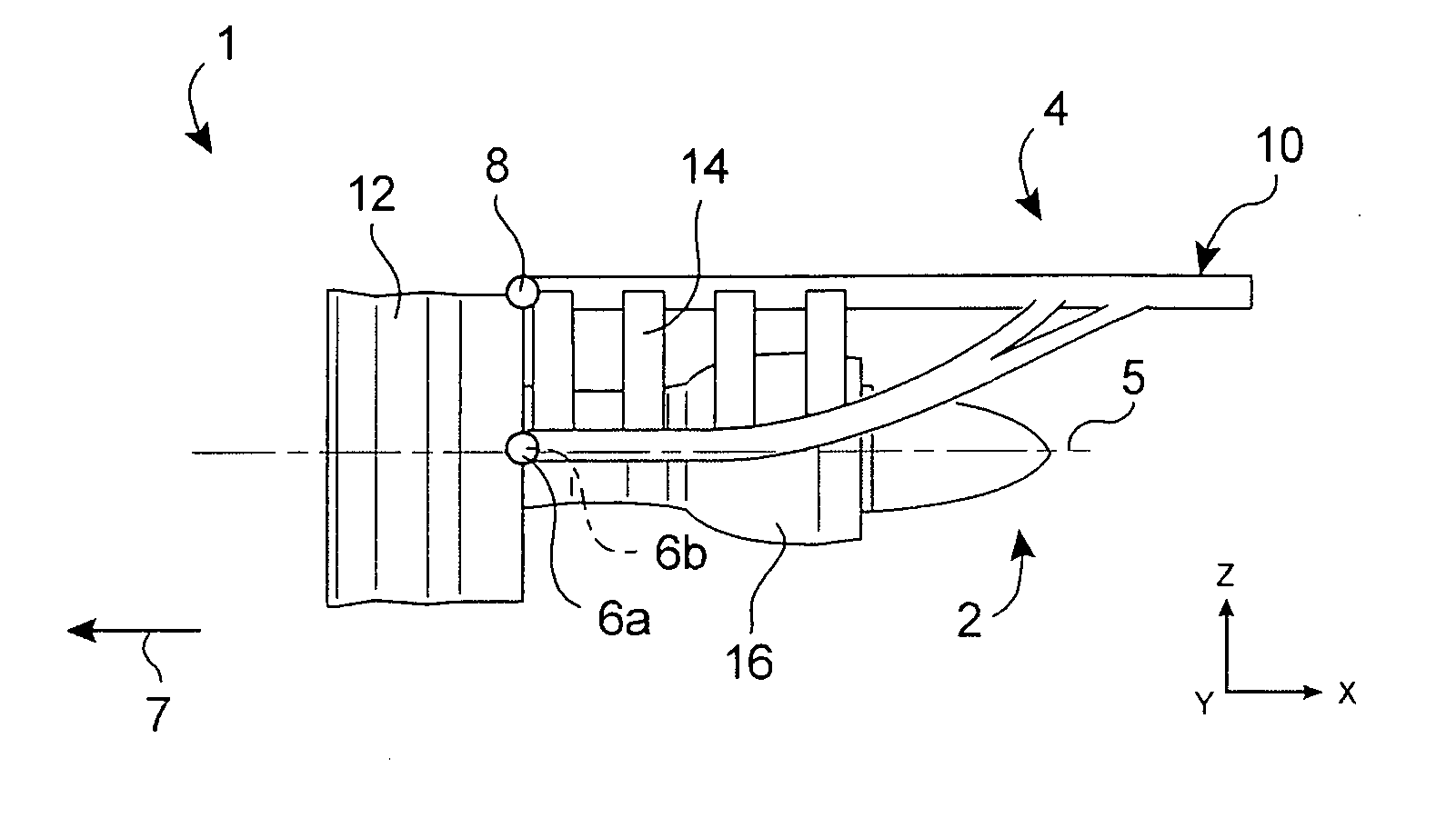
[0044]FIG. 1 shows an engine assembly 1 for an aircraft designed to be fixed under a wing of this aircraft (not shown), this assembly 1 according to one preferred embodiment of this invention comprising a mounting pylon 4.

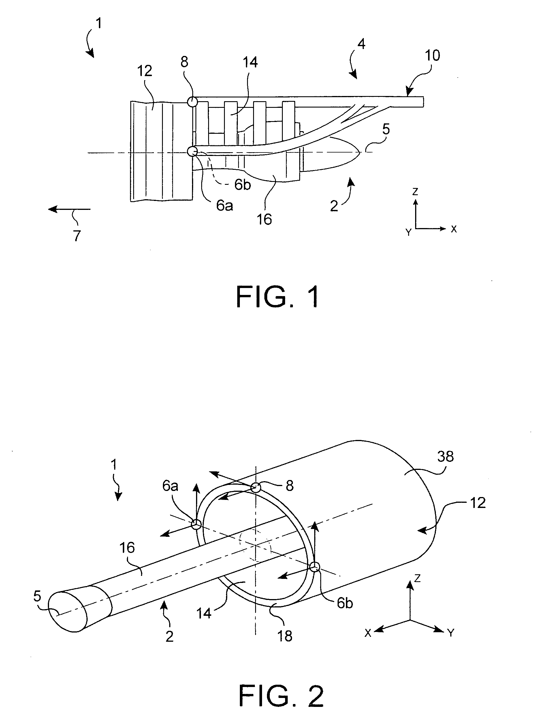
[0045] Globally, the engine assembly 1 is composed of a turbojet 2 and the mounting pylon 4, the mounting pylon being provided in particular with a plurality of engine fasteners 6a, 6b, 8, and a rigid structure 10 carrying these same fasteners (fastener 6b in this FIG. 1 being hidden by fastener 6a). For guidance, note that the assembly 1 will be surrounded by a pod (not shown), and the mounting pylon 4 comprises another series of fasteners (not shown) to suspend this assembly 1 under the aircraft wing.

[0046] Throughout the following description, the convention used is that X is the longitudinal direction of the pylon 4 and is also effectively the longitudinal direction of the turbojet 2, this direction X being parallel to a longitudinal axis 5 of this turbojet 2...


PUM


Abstract

A turbojet-mounting pylon for an aircraft. The pylon includes a rigid structure including a plurality of arcs arranged so as to jointly delimit a part of a fictitious approximately cylindrical surface with a circular section. The plurality of arcs also includes two lateral thrust resisting arcs located on each side of the central box, each of the two lateral arcs being fixed to each arc in the form of an annular portion, and on each side of the central box.

Description

TECHNICAL DOMAIN [0001] This invention relates in general to a turbojet mounting pylon for an aircraft. This type of mounting pylon is also called an EMS (Engine Mounting Structure), that can be used to suspend the turbojet below the aircraft wing, or to fit this turbojet above the same wing. STATE OF PRIOR ART [0002] Such a mounting pylon is designed to form the connecting interface between a turbojet and a wing of the aircraft. It transmits forces generated by its associated turbojet to the structure of this aircraft, and it also enables routing of fuel, electricity, hydraulics and air between the engine and the aircraft. [0003] In order to transmit forces, the pylon comprises a rigid structure, frequently of the “box” type, in other words formed by the assembly of upper and lower spars and side panels connected to each other through transverse ribs. [0004] The pylon is also provided with an engine mounting system inserted between the turbojet and the rigid structure of the pylon,...

Claims


Application Information

Patent Timeline
IPC IPC(8): B64D27/00B64D27/26
CPCB64D2027/264B64D27/26
Inventor DIOCHON, LIONELDURAND, JEROME
Owner AIRBUS OPERATIONS (SAS)
Why Eureka
Try Eureka