Steady state surface mode device for stereoscopic projection

a surface mode and projection technology, applied in the field of motion picture projection, can solve the problems of reducing the amount of light that can be projected on the screen using this technique, affecting the quality of the image,

Inactive Publication Date: 2007-09-06
REAID INC
View PDF18 Cites 106 Cited by
  • Summary
  • Abstract
  • Description
  • Claims
  • Application Information

AI Technical Summary

Problems solved by technology

Faltering attempts were made to deploy circular polarization in the early 1980s for the theatrical cinema, but it was reported that the resultant image crosstalk was too significant for adequate viewing.
The major limitation of the single projector technique compared to dual projection is that single projection has reduced brightness.
Because the amount of light that can be projected on the screen using this technique is so reduced, it can be quite difficult to fill a large screen with enough light to make a good image.
That means that theaters with larger screens—often up to 60 feet wide—cannot use this single projector process and successfully show field-sequential three-dimensional movies.
This binder may cause phase-shifting or birefringence effects that can change the optimum value of the wavelength of reflected circular polarized light.
Such isolation can cause unpleasant ghost images which detract from the enjoyment of the stereoscopic movie.
Traditional dual projection polarizers cannot readily correct for the phase shifts arising from different screen binder materials and eyewear batch-to-batch variations in circular analyzers.

Method used


Image

  • Steady state surface mode device for stereoscopic projection
  • Steady state surface mode device for stereoscopic projection
  • Steady state surface mode device for stereoscopic projection

Examples


Embodiment Construction

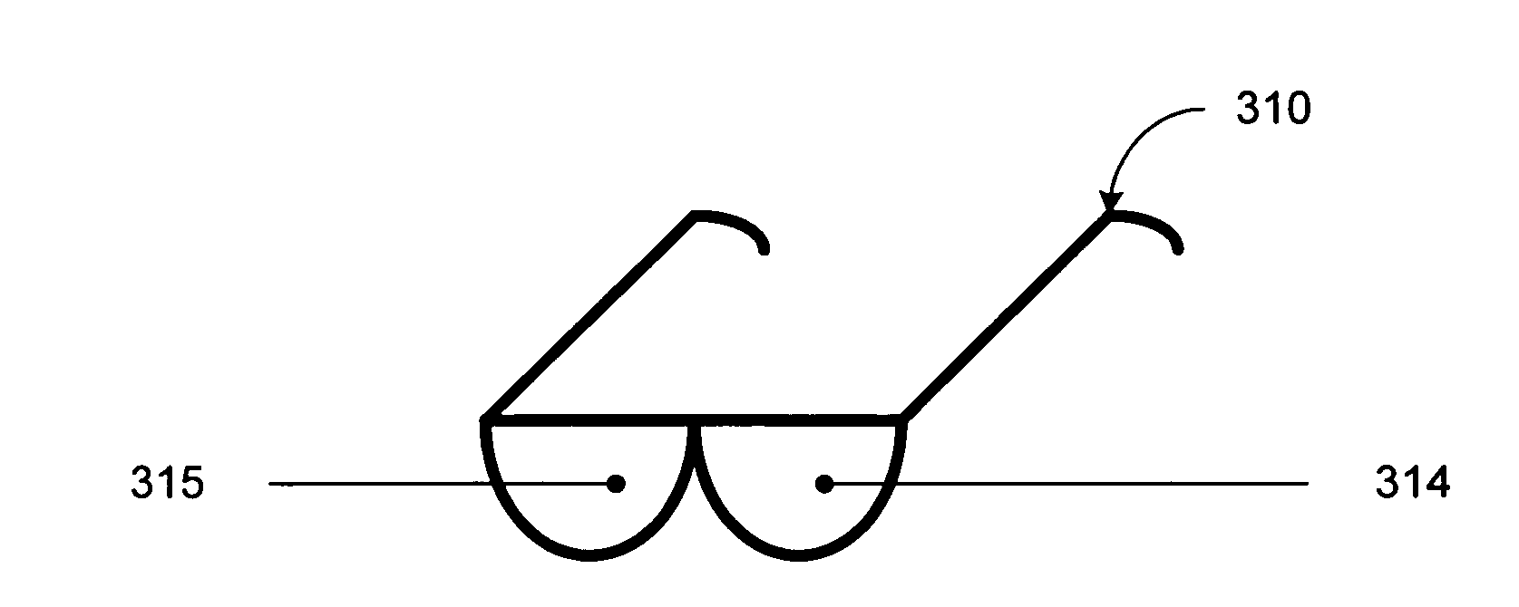
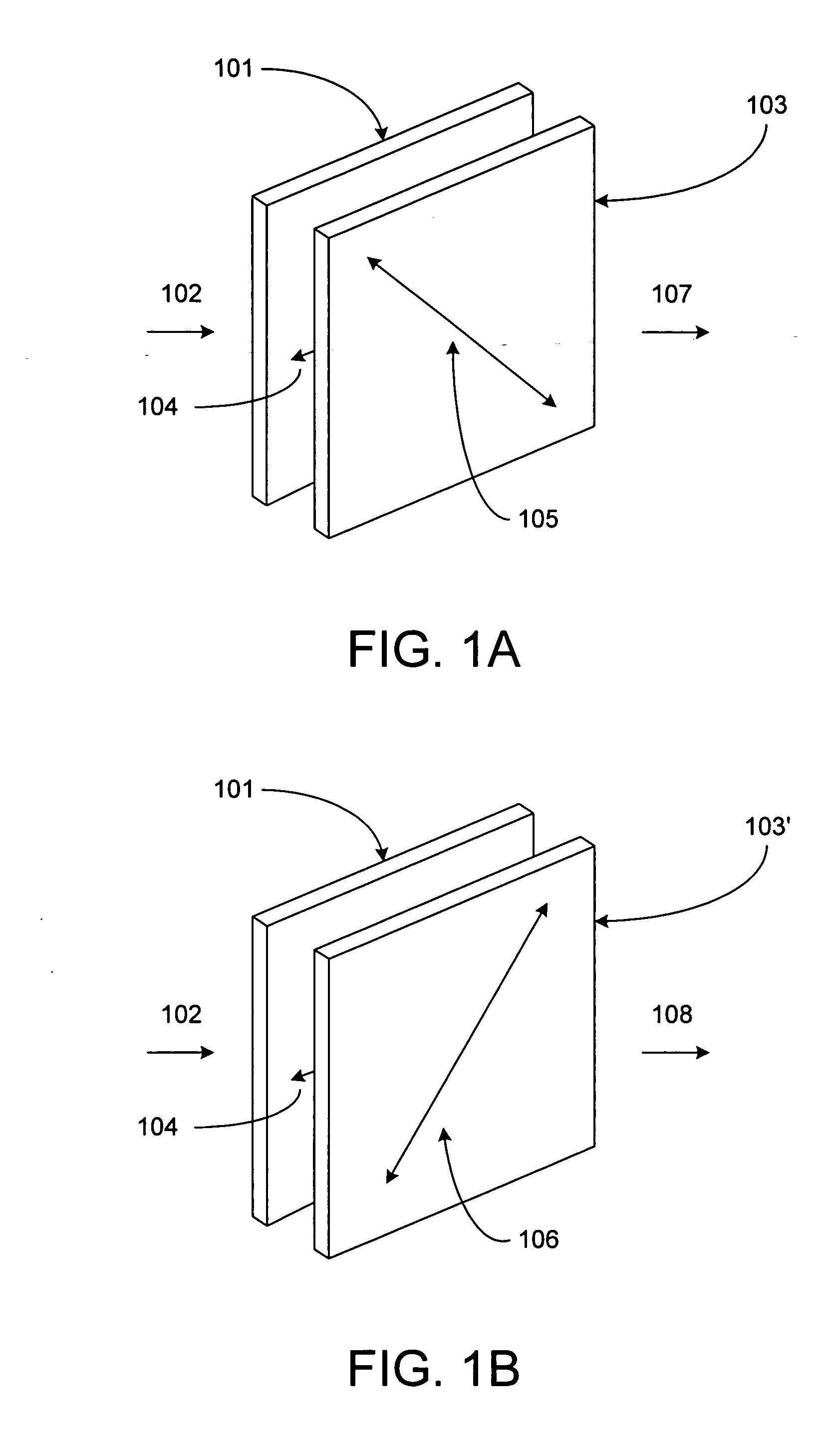
[0024] The present design uses a surface mode device (SMD) where circular polarized light is created through the use of a sheet polarizer in combination with the SMD. This electro-optical modulator is operated in a steady state mode that enables tuning the device to the exact wavelength of the analyzers in the selection device eyewear to optimize image selection and reduce crosstalk. In addition, tuning may be required to correct for any phase shifting resulting from the birefringence produced by projection screen binder materials.

[0025] The SMD is also known in the literature as the pi-cell. The SMD is referred to here as an SMD or a modulator, or an electro-optical modulator, or any combination thereof.

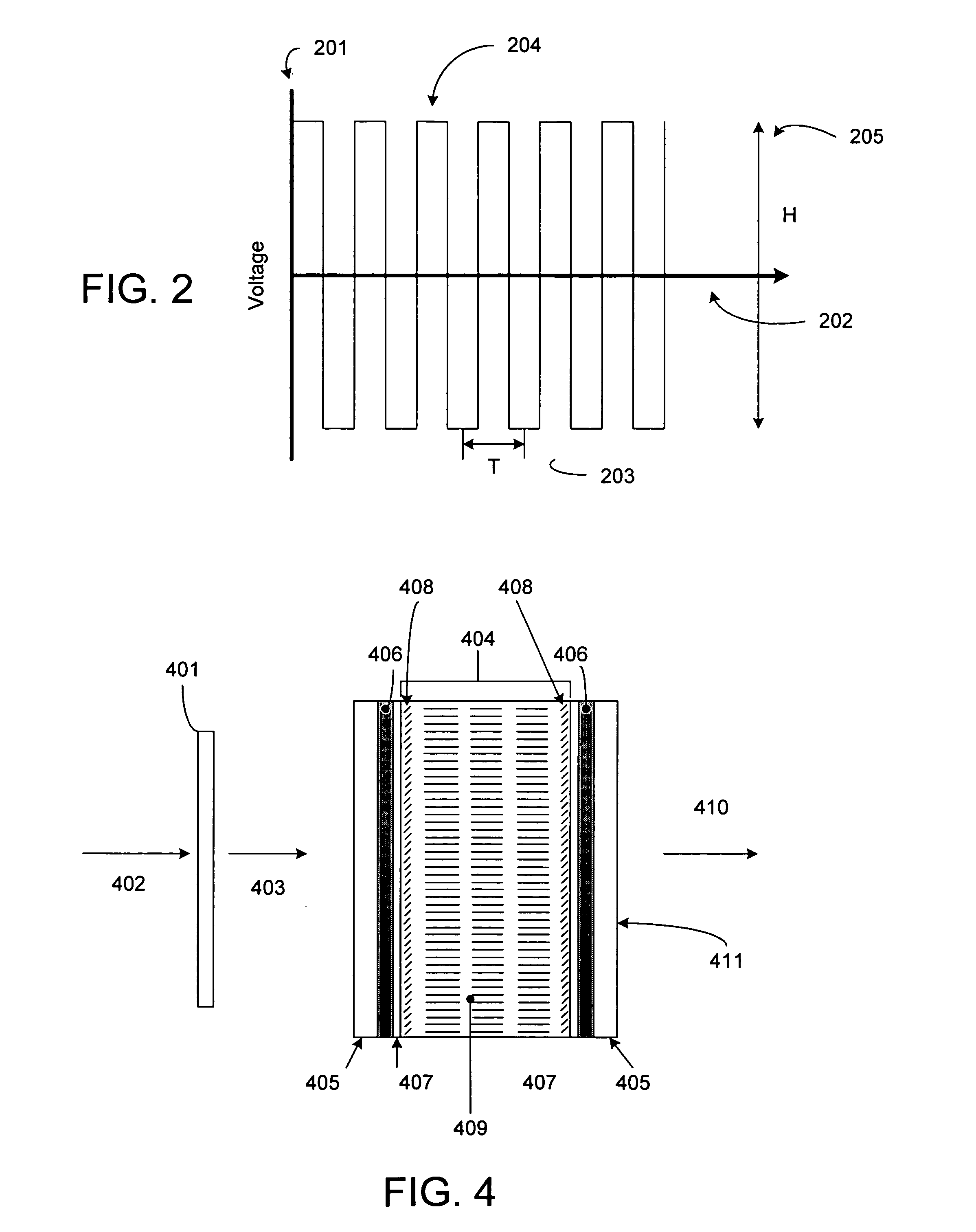
[0026] As noted, due to certain projection brightness constraints, screen size has previously been limited. One solution to the screen size limitation is to use two projectors, thereby doubling the light output and that is the approach taken in this disclosure. The present design ...


PUM


Abstract

A modulator and system used to display motion pictures is provided. The design comprises a sheet polarizer and a SMD electro-optical modulator configured to operate in a steady state (non-switching) mode. The modulator is formed from two substantially parallel relatively clear plates, such as glass, two coatings of a transparent conductor, such as indium tin oxide, located between the two substantially parallel relatively clear plates, two polyamide layers located between the two coatings of the transparent conductor, and a film of liquid crystal material located between the two polyamide layers.

Description

BACKGROUND OF THE INVENTION [0001] 1. Field of the Invention [0002] The present invention relates generally to the art of motion picture projection, and more specifically to a device to produce tuned circularly polarized light for stereoscopic image selection for motion pictures using multiple projectors or multiple projection lenses or optics. [0003] 2. Description of the Related Art [0004] The projection of stereoscopic motion pictures by means of polarization is a well established art with many contributors. A commercial milestone was reached in the 1939 New York World's Fair with the projection of a stereoscopic motion picture using linear polarized light sheet filters for image selection using two 35-millimeter projectors. That system has been used, with relatively minor modifications, up until the present time. This design was used in the early 1950s for the projection of 3-D motion pictures in the theatrical cinema, and has been used for the past 20 years or so in location-ba...

Claims


Application Information

Patent Timeline
Patent Type & Authority Applications(United States)
IPC IPC(8): G03B21/14
CPCG03B21/32H04N13/0459H04N13/0434G03B35/26H04N13/337H04N13/363G03B21/00G03B21/14
Inventor LIPTON, LENNY
Owner REAID INC
Why Eureka
Try Eureka