
Flexure including controlled static attitude and load point contact

Inactive Publication Date: 2007-09-06
SEAGATE TECH LLC
View PDF21 Cites 6 Cited by
  • Summary
  • Abstract
  • Description
  • Claims
  • Application Information

AI Technical Summary

Benefits of technology

[0010] Other features and benefits that characterize embodiments of the present invention will be apparent upon reading the following detailed description and review of the associated drawings.

Problems solved by technology

Improving performance and reducing costs are conflicting objectives and, therefore, can be difficult to achieve.
One of the most common suspension assembly issues is the position of the slider relative to the medium.
Vertical separation between slider and the data track on the medium is one type of position issue.
If the slider is too far above the data track the electromagnetic interaction between the slider and the medium will be weak, resulting in poor data storage.
If the slider is too close to the medium then mechanical contact between the slider and the spinning medium can become too frequent, or too severe, or both, (for non-contact applications) thereby affecting the reliability of the disc drive.
Poor vertical separation between the slider and the medium can be the result of deviations of the load force applied by the load beam.
Besides deviations in load force, poor vertical separation between the slider and the medium can be the result of the suspension failing to present the bearing surface of the slider in a parallel fashion to the surface of the medium.
This gimbal deflection results in moments, or torques, opposing the deflection.
Specifically, shock and vibration can be the most serious.
Small sized disc drives that are mounted in portable consumer devices (e.g., notebook computers and portable music players and other types of devices) are especially susceptible to shock and vibration.
It is fairly easy to accidentally drop a disc drive or the system in which it is mounted.
Such accidental drops can cause significant shock pulses to pass through the various components within the disc drive and can cause the slider to lift away from the medium, and then crash back against the medium causing severe damage to the medium, head, or both.
Such separation can deform and damage the gimbal.

Method used


Image

  • Flexure including controlled static attitude and load point contact
  • Flexure including controlled static attitude and load point contact
  • Flexure including controlled static attitude and load point contact

Examples


Embodiment Construction

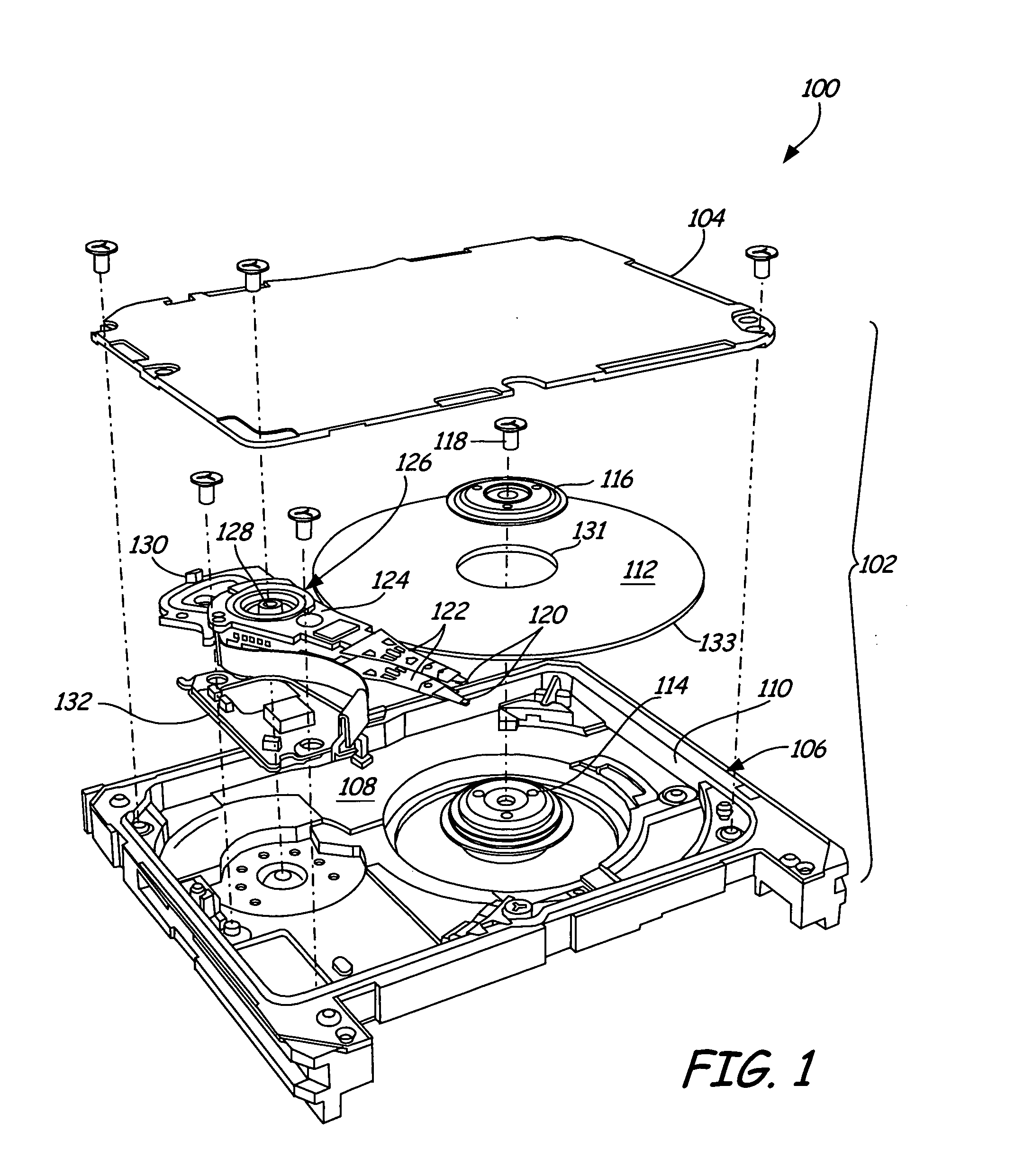
[0028]FIG. 1 is an exploded perspective view of a disc drive 100 in which embodiments of the present invention are useful. Disc drives are common data storage systems. One or more embodiments of the present invention are also useful in other types of data storage and non-data storage systems.

[0029] Disc drive 100 includes a housing 102 having a cover 104 and a base 106. As shown, cover 104 attaches to base 106 to form an enclosure 108 enclosed by a perimeter wall 110 of base 106. The components of disc drive 100 are assembled to base 106 and are enclosed in enclosure 108 of housing 102. As shown, disc drive 100 includes a disc or medium 112. Although FIG. 1 illustrates medium 112 as a single disc, those skilled in the art should understand that more than one disc can be used in disc drive 100. Medium 112 stores information in a plurality of circular, concentric data tracks and is mounted on a spindle motor assembly 114 by a disc clamp 116 and pin 118. Spindle motor assembly 114 rot...


PUM


Abstract

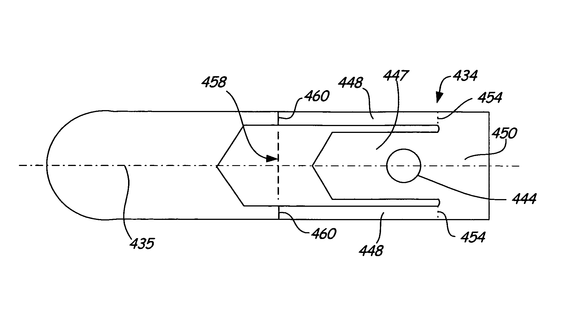
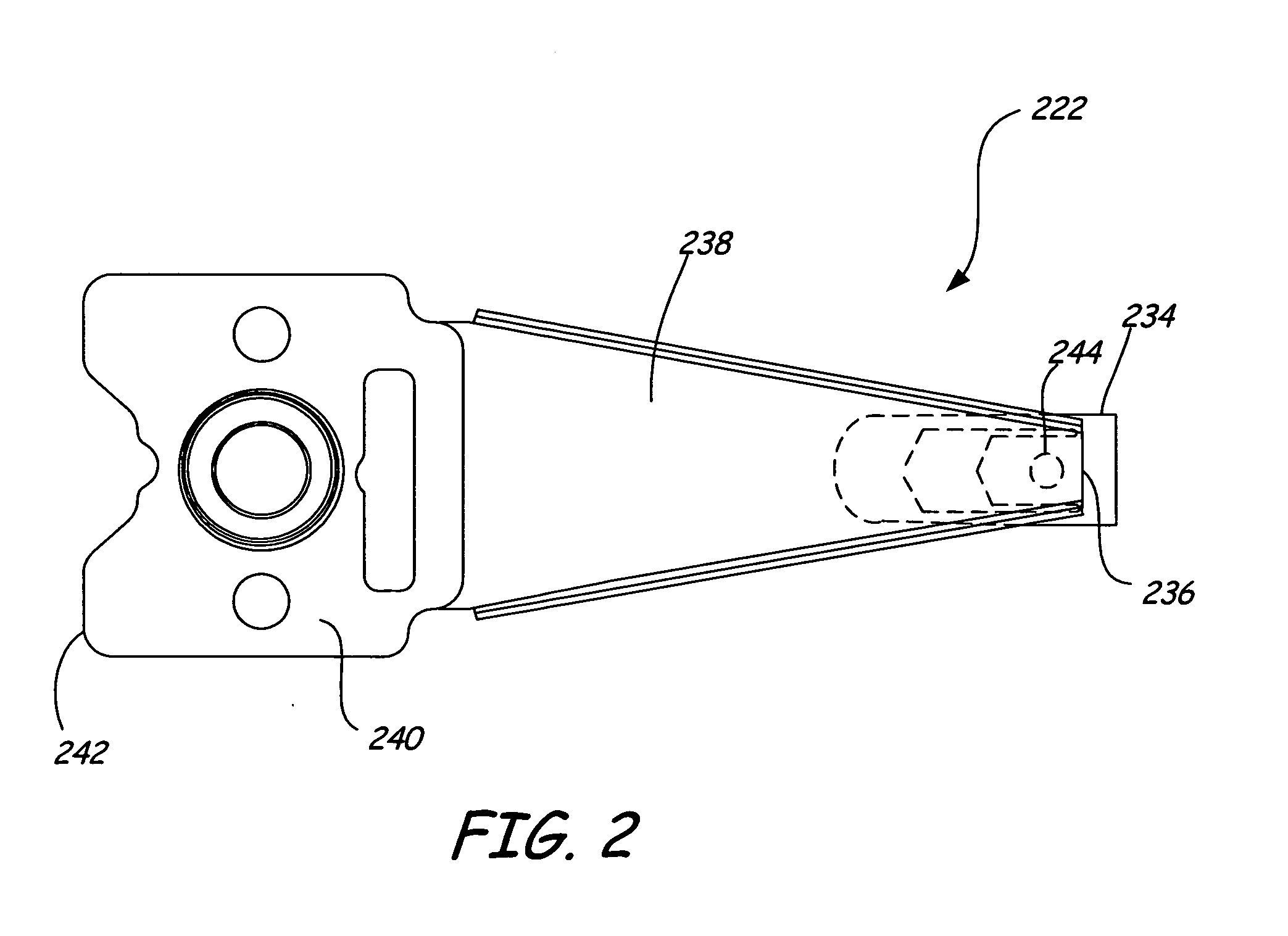
A flexure includes a base and a pair of beams coupled to the base at fixed-ends. The pair of beams are joined by a cross-beam at free-ends of the beams. A tongue extends from the cross-beam between the pair of beams towards the base. The flexure also includes a bend in each of the beams, which displaces the free ends out-of-plane relative to the fixed ends.

Description

FIELD OF THE DISCLOSURE [0001] The disclosure relates generally to flexures, and more particularly but not by limitation to flexures for data storage systems. BACKGROUND OF THE DISCLOSURE [0002] A typical data storage system includes a housing that encloses a variety of components. For example in a disc drive, the components include at least one rotating disc having data on one or more surfaces that are coated with a medium for storage of digital information in a plurality of circular, concentric data tracks. The disc(s) are mounted on a spindle motor that causes the disc(s) to spin and the data surfaces of the disc(s) to pass under respective hydrodynamic bearing slider surfaces. The sliders carry transducers, which write information to and read information from the data surfaces of the disc(s). An actuator mechanism moves the sliders from track to track across the surfaces of the discs under control of electronic circuitry. The actuator mechanism includes a track accessing arm and...

Claims


Application Information

Patent Timeline
IPC IPC(8): G11B5/48
CPCG11B5/4833
Inventor HAGEN, TRACY MICHAEL
Owner SEAGATE TECH LLC
Learn More