Three-dimensional (3D) hydrodynamic focusing using a microfluidic device

a microfluidic device and hydrodynamic focusing technology, applied in the field of three-dimensional (3d) hydrodynamic focusing, can solve the problems of impracticality or less accuracy, and achieve the effect of more reliable single-molecule sensitivity

Inactive Publication Date: 2009-03-12
PENN STATE RES FOUND
View PDF4 Cites 76 Cited by
  • Summary
  • Abstract
  • Description
  • Claims
  • Application Information

AI Technical Summary

Benefits of technology

[0006]Three dimensional (3D) hydrodynamic focusing was achieved in a microfluidic device. A sample flow and a vertical focusing sheath flow were passed through a curved channel section, allowing hydrodynamic focusing (i.e. flow compression) of the sample flow in a direction normal to the plane of the sample flow, which may be normal to a substrate. This process may be termed microfluidic drifting. A second horizontally focusing sheath flow can be used to achieve hydrodynamic focusing in the plane of s...

Problems solved by technology

Hydrodynamic focusing devices using microfluidic drifting may be used in many applications ...

Method used


Image

  • Three-dimensional (3D) hydrodynamic focusing using a microfluidic device
  • Three-dimensional (3D) hydrodynamic focusing using a microfluidic device
  • Three-dimensional (3D) hydrodynamic focusing using a microfluidic device

Examples


example device fabrication

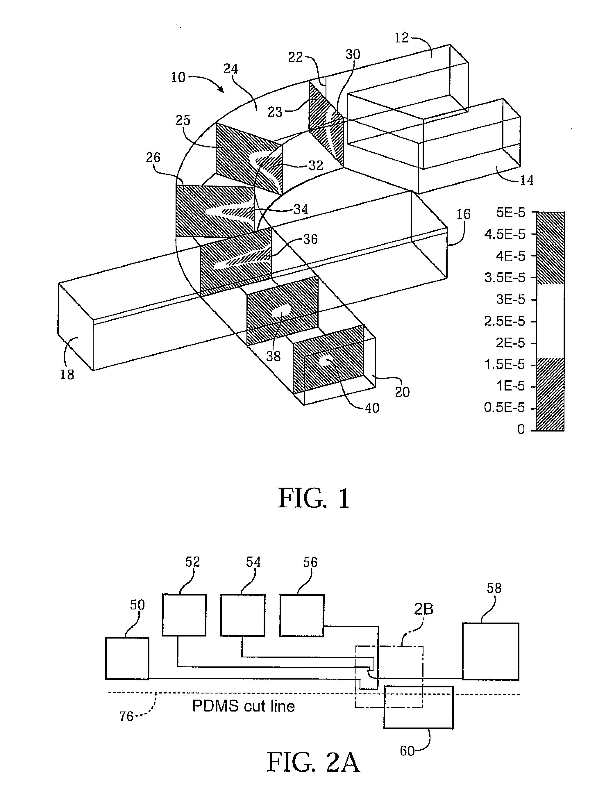
[0053]Polydimethylsiloxane (PDMS) microchannels were fabricated using a standard soft lithography technique. The master mold for the soft lithography was made on a silicon wafer (TechGophers, Chino Hills, Calif.) by Deep Reactive Ion Etching (DRIE, Adixen, Hingham, Mass.). The positive photoresist Shipley 1827 (MicroChem, Newton, Mass.) was lithographically patterned on the silicon wafer to act as a mask for DRIE, and the etch depth was set at 75 μm. The final mold depth was measured using a profilometer (KLA-Tencor, San Jose, Calif.) to ensure that the desired depth had been achieved.

[0054]The silicon mold was subsequently coated with 1H,1H,2H,2H-perfluorooctyltrichlorosilane (Sigma Aldrich, St. Louis, Mo.) after DRIE, in order to reduce surface energy and hence the damage to the PDMS channel during the demolding process. A smooth surface of the PDMS channel sidewall reduces scattering losses and improves the quality of side-view epifluorescence microscopy. Sylgard™ 184 Silicone El...


PUM


Abstract

A microfluidic device comprises inlets for a sample flow and an out-of-plane focusing sheath flow, and a curved channel section configured to receive the sample flow and out-of-plane focusing sheath and to provide hydrodynamic focusing of the sample flow in an out-of-plane direction, the out-of-plane direction being normal to a plane including the curved channel.

Description

REFERENCE TO RELATED APPLICATION[0001]This application claims priority from U.S. Provisional Patent Application Ser. No. 60 / 971,054, filed Sep. 10, 2007, the entire content of which is incorporated herein by reference.GOVERNMENT SUPPORT[0002]This invention was made with government support under awarded by Contract No. ECCS-0609128 awarded by the National Science Foundation. The government has certain rights in the invention.FIELD OF THE INVENTION[0003]The present invention relates to hydrodynamic focusing.[0004]BACKGROUND OF THE INVENTION[0005]Hydrodynamic focusing is used to compress a sample flow, typically in two dimensions. Improved methods of hydrodynamic focusing would be useful for numerous applications, such as flow cytometry and single molecule fluorescence.SUMMARY OF THE INVENTION[0006]Three dimensional (3D) hydrodynamic focusing was achieved in a microfluidic device. A sample flow and a vertical focusing sheath flow were passed through a curved channel section, allowing h...

Claims


Application Information

Patent Timeline
IPC IPC(8): G01N21/01C12M1/34G01N21/53G01N21/64B01L3/00
CPCB01F13/0062B01L3/502776B01L2200/0636B01L2300/0816B01L2300/0861Y10T436/2575B01L2400/0487B01L2400/084G01N15/1404G01N21/6458B01L2400/0409B01F33/3011
Inventor HUANG, TONY JUNMAO, XIAOLE
Owner PENN STATE RES FOUND
Why Eureka
Try Eureka