
Wind turbine blade deflection control system

Inactive Publication Date: 2008-05-01
BOSCHE JOHN VANDEN
View PDF10 Cites 78 Cited by
  • Summary
  • Abstract
  • Description
  • Claims
  • Application Information

AI Technical Summary

Benefits of technology

[0007] Each of the above types of sensors has advantages and disadvantages. The strain gage and accelerometer approaches have the advantage that they track blade position all the time and can be used to monitor blade loads as well as deflection. A system that measures blade load is described in WIPO patent application WO 01 / 33075 (which is incorporated herein by reference). However, the signal from the strain gage or accelerometer can tend to drift and any small error in the signal will be compounded as the signal is integrated over time. Therefore, the best solution may be a combination of a strain gage or accelerometer in the blade combined with a stationary sensor on the tower that is used to “zero” the output from the strain gages or accelerometer once per blade revolution.
[0008] The controller of the present invention uses the output from the blade deflection sensor to determine if the blade is in danger of striking the tower. If the controller determines that a tower strike is possible, then it takes some control action to avoid a tower strike. The control action could take several possible forms. The controller could pitch the blades if the turbine is a variable pitch machine. If the blades are independently pitchable, then the preferred method is to pitch only the blade or blades that are in danger of a tower strike. Some wind turbines utilize ailerons or partial span pitch rather than full span pitch, and the same control objectives can be met using the aileron or partial span pitch rather than the full span pitch. If the wind turbine has fixed pitch blades, then it may be possible to yaw the turbine in order to avoid a tower strike. Yawing the turbine takes the rotor out of the wind and reduces loads on the blades. Yawing can also cause gyroscopic loads on the blades that tend to deflect them toward or away from the tower. Of course, it would be necessary to yaw the turbine in the appropriate direction in order to deflect the blades away from the tower using gyroscopic forces. A final control action that could be taken is to apply the brakes and stop the wind turbine entirely. Almost all wind turbines have emergency stopping and normal stopping procedures. Depending on the severity of the risk of a tower strike, the controller would determine whether a normal or emergency stop is necessary.

Problems solved by technology

However, the signal from the strain gage or accelerometer can tend to drift and any small error in the signal will be compounded as the signal is integrated over time.
Yawing can also cause gyroscopic loads on the blades that tend to deflect them toward or away from the tower.

Method used


Image

  • Wind turbine blade deflection control system
  • Wind turbine blade deflection control system
  • Wind turbine blade deflection control system

Examples


Embodiment Construction

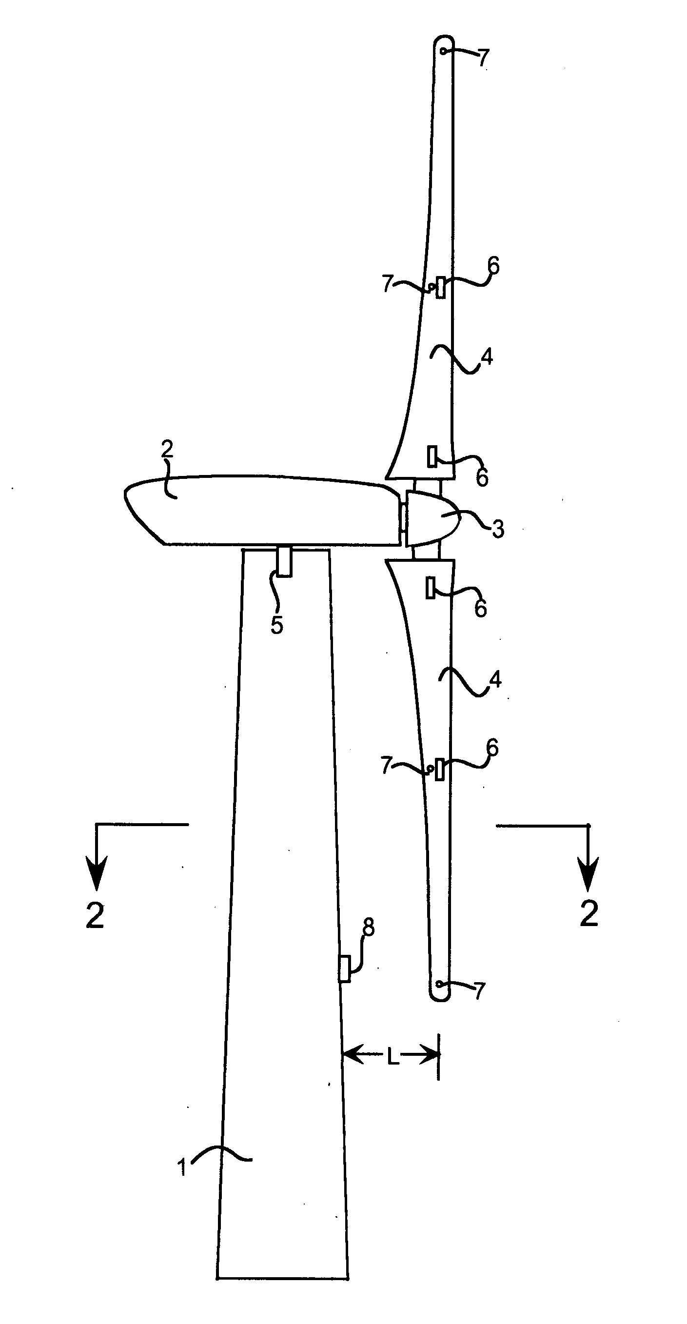
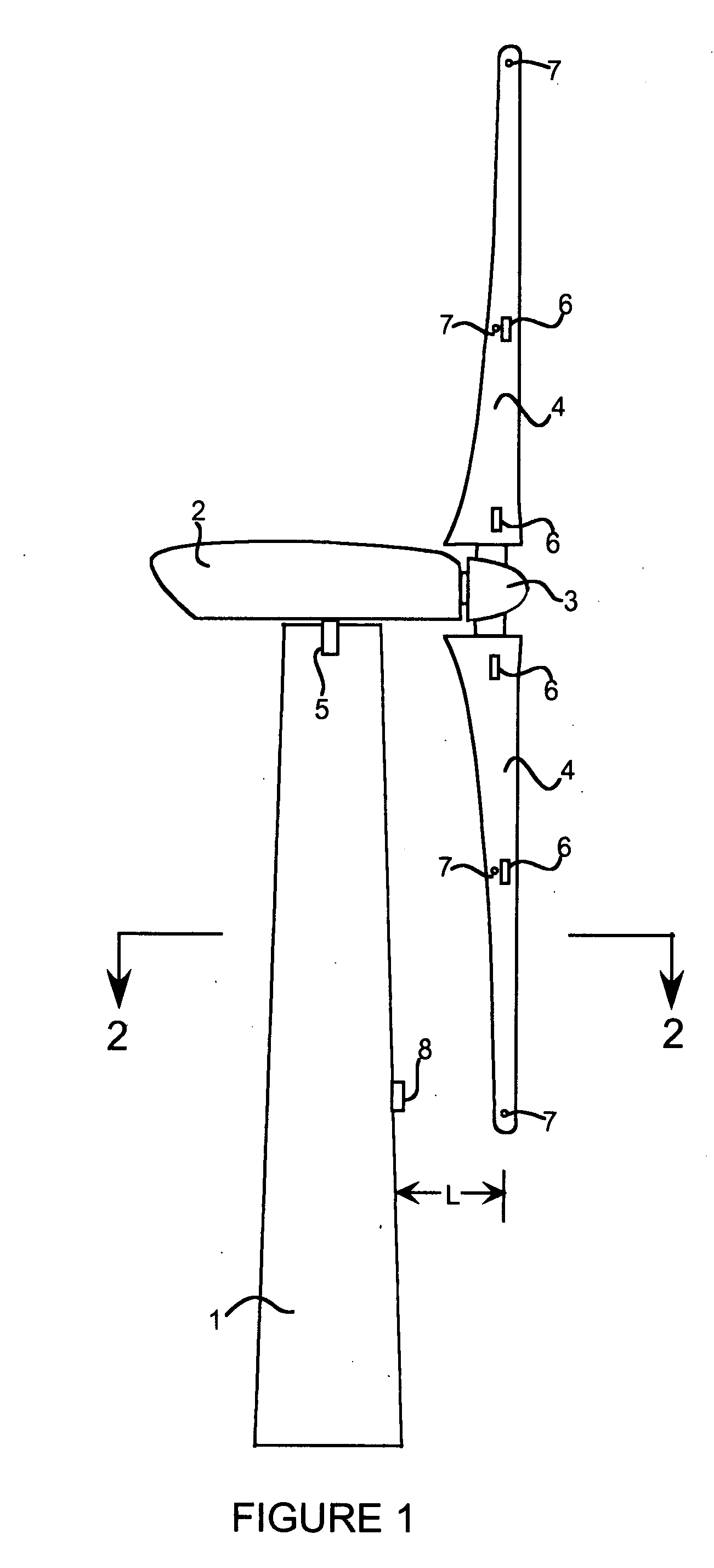
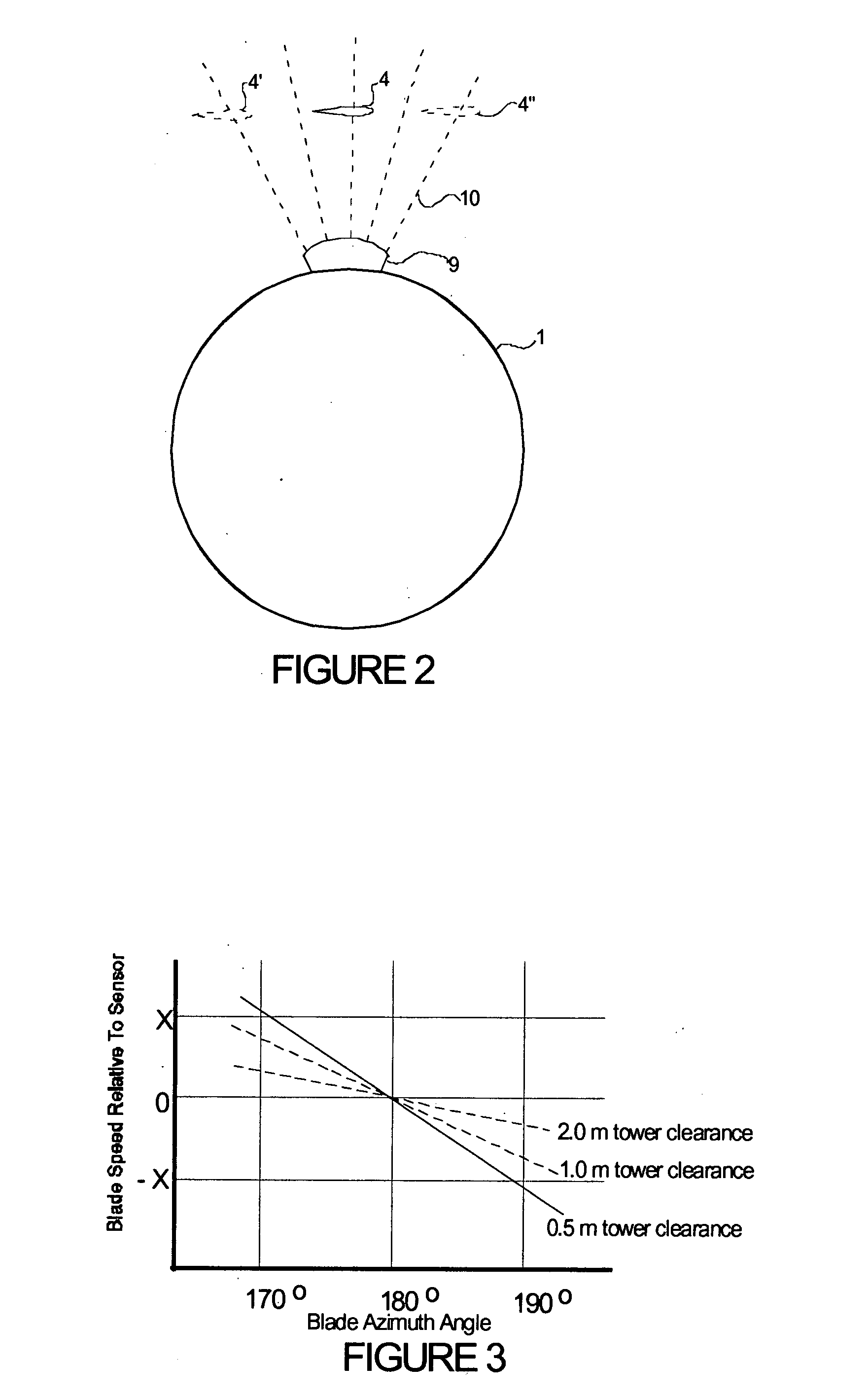
[0013] The wind turbine of the present invention is shown in FIG. 1 and includes a tower 1 with a nacelle 2 at the top of the tower 1. The nacelle 2 contains the main shaft, associated bearings, the gearbox, the generator, and any associated hydraulic or control equipment that is necessary. Each wind turbine includes different components in the nacelle 2 and these components are not shown in FIG. 1 because they do not form a part of the present invention. Attached to the nacelle 2 is a hub 3 with blades 4 attached to the hub for rotation therewith relative to the nacelle 2. The wind turbine can include any number of blades 4, although two or three blades tend to be the most common number of blades on most commercially available wind turbines. Furthermore, the blades 4 may be oriented so that they are either upwind or downwind of the tower 1 during operation. The present invention is more critical for wind turbines with an upwind configuration, although downwind turbines have been kn...


PUM


Abstract

A wind turbine with a sensor that measures the out-of-plane deflection of the blades and a controller that uses the signal from the sensor to determine the risk of a tower strike. The controller takes any necessary action to prevent a tower strike when it determines that the risk of a strike is high. The sensor can include strain gages or accelerometers mounted on the blades or it can include a fixed sensor mounted on the side of the tower to measure tower clearance as the blade passes by. The control action taken can include pitching blades, yawing the nacelle, or stopping the turbine. The controller is preferably a fuzzy logic controller.

Description

RELATED PATENTS [0001] This application claims priority to U.S. patent application Ser. No. 10 / 253,134 which is incorporated herein by reference.BACKGROUND OF THE INVENTION [0002] This invention relates to a control system for wind turbines and particularly to a control system that limits blade deflection to avoid tower strikes. [0003] Wind turbines have long been used to generate electricity from the wind. The most common type of wind turbine is the horizontal axis turbine. Horizontal axis wind turbines have one or more blades (but most commonly 2 or 3 blades) attached to a shaft that rotates about a horizontal axis. On the opposite end of the shaft from the blades is a gearbox and generator. When wind passes over the blades, the shaft rotates and the generator makes electricity. Such wind turbines have been extensively used in California for the past 20 years and are being installed in large numbers all around the world. [0004] One of the primary concerns in the design of a wind t...

Claims


Application Information

Patent Timeline
IPC IPC(8): F03D7/00F03D7/02
CPCF03D7/0204F03D7/0224F03D7/0288Y02E10/723F05B2270/33F05B2270/707F05B2270/808F03D7/046F05B2270/17Y02E10/72
Inventor BOSCHE, JOHN VANDEN
Owner BOSCHE JOHN VANDEN
Learn More