Information recording and reproducing apparatus, and information recording method

a technology which is applied in the field of information recording and reproducing apparatus, information recording method, optical disk apparatus, etc., can solve the problems of optical removal of disturbance, deterioration of readout signals, etc., and achieve the reduction of disturbance in the amount of light transmitted through the non-readout layer, optical removal is not possible, and the effect of optical removal

Inactive Publication Date: 2007-09-06
HITACHI LTD
View PDF4 Cites 6 Cited by
  • Summary
  • Abstract
  • Description
  • Claims
  • Application Information

AI Technical Summary

Benefits of technology

[0016] In accordance with the present invention, disturbance in the amount of light transmitted through the non-readout layer, which cannot be optically removed, can be reduced.

Problems solved by technology

With regard to a next-generation multi-layer optical disk, one of the major problems associated with its multilayer structure is that readout signals deteriorate due to interlayer crosstalk from a layer (non-readout layer) other than the readout layer.
However, with regard to the disturbance in the amount of light transmitted through the non-readout layer, since the optical spot from the readout layer is influenced by the signal disturbance, it is impossible to remove the disturbance optically.

Method used


Image

  • Information recording and reproducing apparatus, and information recording method
  • Information recording and reproducing apparatus, and information recording method
  • Information recording and reproducing apparatus, and information recording method

Examples


embodiment 1

[Embodiment 1]

[0048] A first embodiment of the invention will be described by referring to FIGS. 4 to 12.

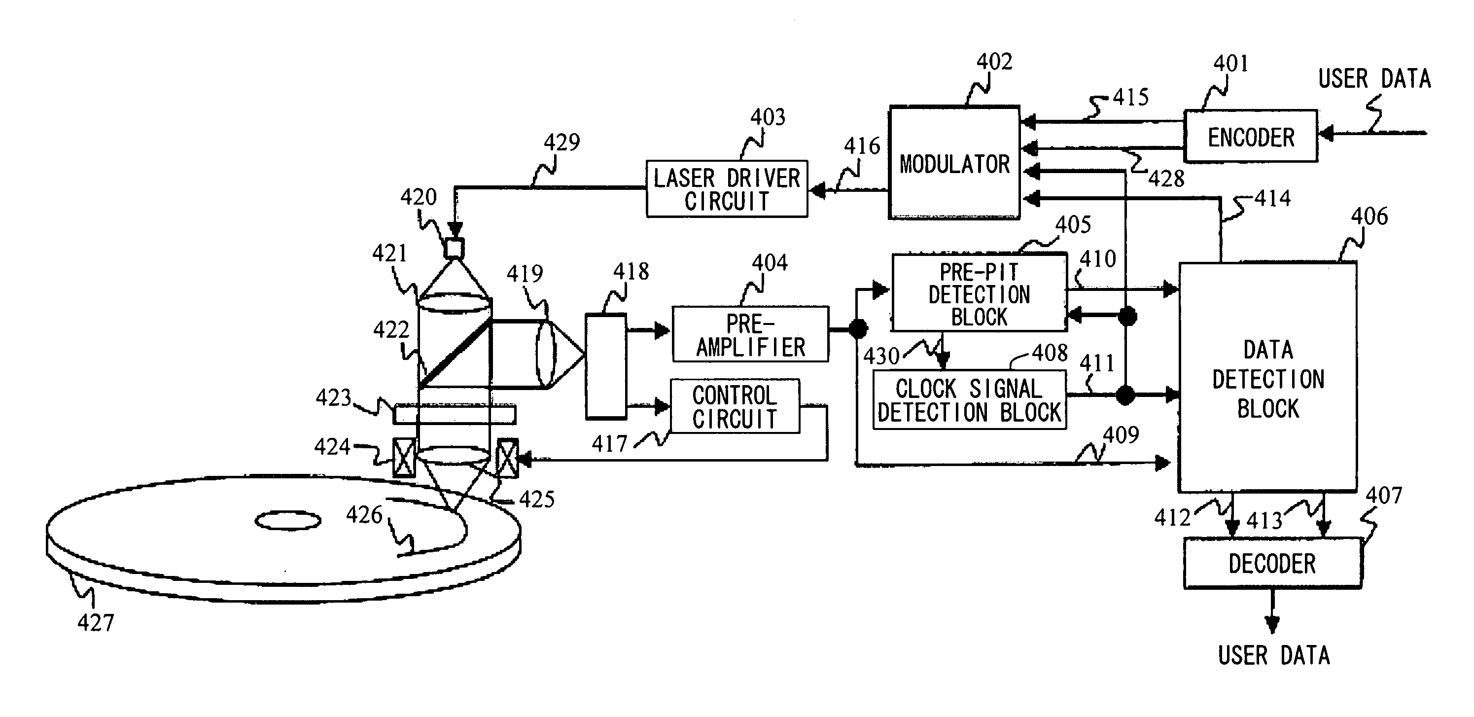
[0049]FIG. 4 shows a block diagram of an optical information recording and reproducing apparatus according to the invention, in a case where a data cell has one mark. Light emitted by a semiconductor laser 420 is collimated into parallel light by a collimator lens 421. The parallel light passes through a polarized beam splitter 422 and further through a 1 / 4-wavelength plate 423, whereby the linear polarized light is converted into circular polarized light. The circular polarized light is focused on a rotating disk-type recording medium 427 by an object lens 425, forming a small spot thereon. Light reflected by the recording medium 427 passes through the object lens 425 again and further through the 1 / 4-wavelength plate 423, whereby the light is converted into linear polarized light with its direction of polarization rotated by 90 degrees with respect to the incident light. The l...

embodiment 2

[Embodiment 2]

[0082] A second embodiment of the invention will be described with reference to FIGS. 22 to 24. FIG. 22 shows a block diagram of an optical information recording and reproducing apparatus according to the invention in a case where a data cell contains one or a plurality of marks. The apparatus differs from that of FIG. 4 only in the encoder, modulator, and decoder. While the encoder 401 outputs the front- and rear-edge positions, an encoder 1701 outputs an NRZI (Non Return to Zero Inverted) codeword 1704. In accordance with such modification, a modulator 1702 is modified to receive the NRZI codeword 1704 and output a signal 416, and a decoder 1703 is modified to receive a detected NRZI codeword 1705 and output user data. By having the encoder to output the NRZI codeword, the extension of the data cell structure for improving recording efficiency, such as adapting the data cell to contain a plurality of marks or having a mark to appear over the border between data cells...

embodiment 3

[Embodiment 3]

[0089] Referring to FIGS. 26, 27, 28, and 29, another method for detecting a mark length and a mark center position through a signal level and a differential zero cross point of a signal will be described. FIGS. 26 and 27, which are used in the present embodiment instead of FIGS. 7 and 8, show the correspondence between user data and data cells. In FIGS. 26 and 27, user data and data cells are associated by using a specific interval A that is one half the A in FIGS. 7 and 8 so that the number of data cell regions is doubled. For codewords having marks with lengths that are odd-number multiples of 2A′ , the mark position is shifted by A. A mark center detection interval is A / 2=A′ when detecting a center position of a mark in each data cell in a data cell sequence converted from user data using FIGS. 7 and 8 (for example, the difference between a center position of a mark having a length 7A′ and a center position of a mark having a length 8A, both having the same front e...


PUM

PropertyMeasurementUnit
distanceaaaaaaaaaa
distanceaaaaaaaaaa
refractive indexaaaaaaaaaa

Abstract

Interlayer crosstalk from a layer (non-readout layer) other than a readout layer, which poses a problem for a next-generation multi-layer optical disk, is reduced. A plurality (t) of tables showing a correspondence between user data and combinations of length, position, and total area of one or a plurality of marks in the user data are used. The possible range of the total mark area is varied depending on the tables. The tables containing user data and combinations of the length, position, and total area of the marks are switched by determining between what values in a number (t-l) of combinations of thresholds of mark areas the total area value of the marks contained in the predetermined number of past data cells (m) falls. The amount of disturbance in mark area is reduced by restricting the range of the area of a subsequent mark that is to appear.

Description

CLAIM OF PRIORITY [0001] The present application claims priority form Japanese application JP 2006-055108 filed on Mar. 1, 2006, the content of which is hereby incorporated by reference into this application. BACKGROUND OF THE INVENTION [0002] 1. Field of the Invention [0003] The present invention relates to a method and apparatus for recording and reproducing information on a medium, using changes in optical characteristics. Particularly, it relates to an optical disk apparatus. [0004] 2. Background Art [0005] As a method for increasing the areal density of an optical disk, Non-patent Document 1 proposes a SCIPER (Single Carrier Independent Pit Edge Recording) method by which marks are recorded on a disk surface at equal intervals, front- and rear-edge positions are independently-varied, their positional changes are observed in the form of changes in multi-levels at specific detecting points, and information is read. [0006] Referring to FIG. 1, the principle of the SCIPER method ac...

Claims


Application Information

Patent Timeline
Patent Type & Authority Applications(United States)
IPC IPC(8): G11B7/0045
CPCG11B7/0045G11B7/005G11B20/10009G11B2220/2537G11B20/1426G11B20/22G11B2007/0013G11B20/14
Inventor KONDOU, MASAHARUMAEDA, TAKESHI
Owner HITACHI LTD
Why Eureka
Try Eureka