A multi-component bat and assembly process

a bat and multi-component technology, applied in the field of multi-component bats, can solve the problems of metal bats having certain disadvantages, metal bats vibrating, long hits, etc., and achieve the effect of reducing the speed of vibration traveling

a bat and multi-component technology, applied in the field of multi-component bats, can solve the problems of metal bats having certain disadvantages, metal bats vibrating, long hits, etc., and achieve the effect of reducing the speed of vibration traveling

US20070207882A1Active Publication Date: 2007-09-06VAN NGUYEN THU

Image

  • A multi-component bat and assembly process
  • A multi-component bat and assembly process
  • A multi-component bat and assembly process

Examples


Embodiment Construction

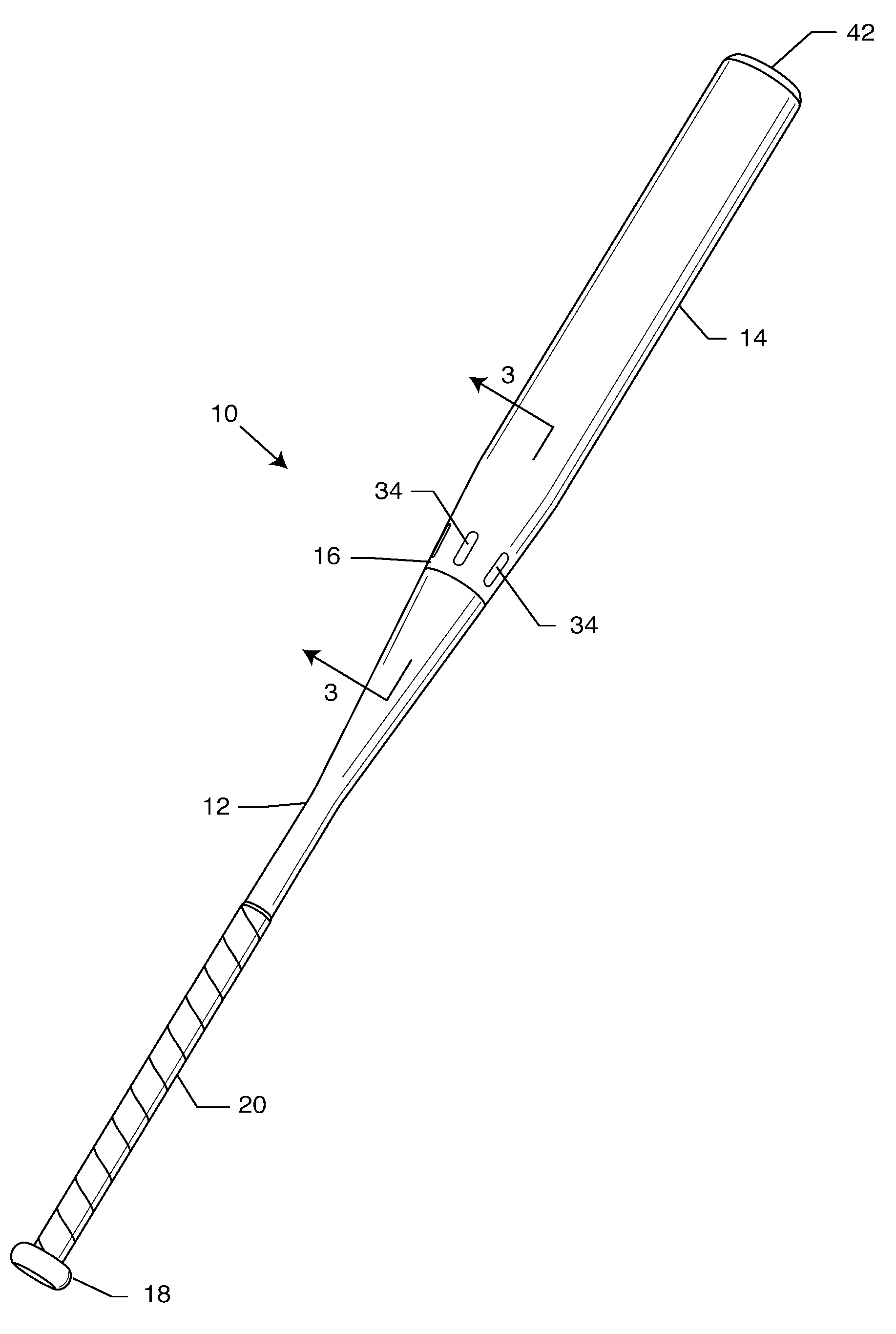
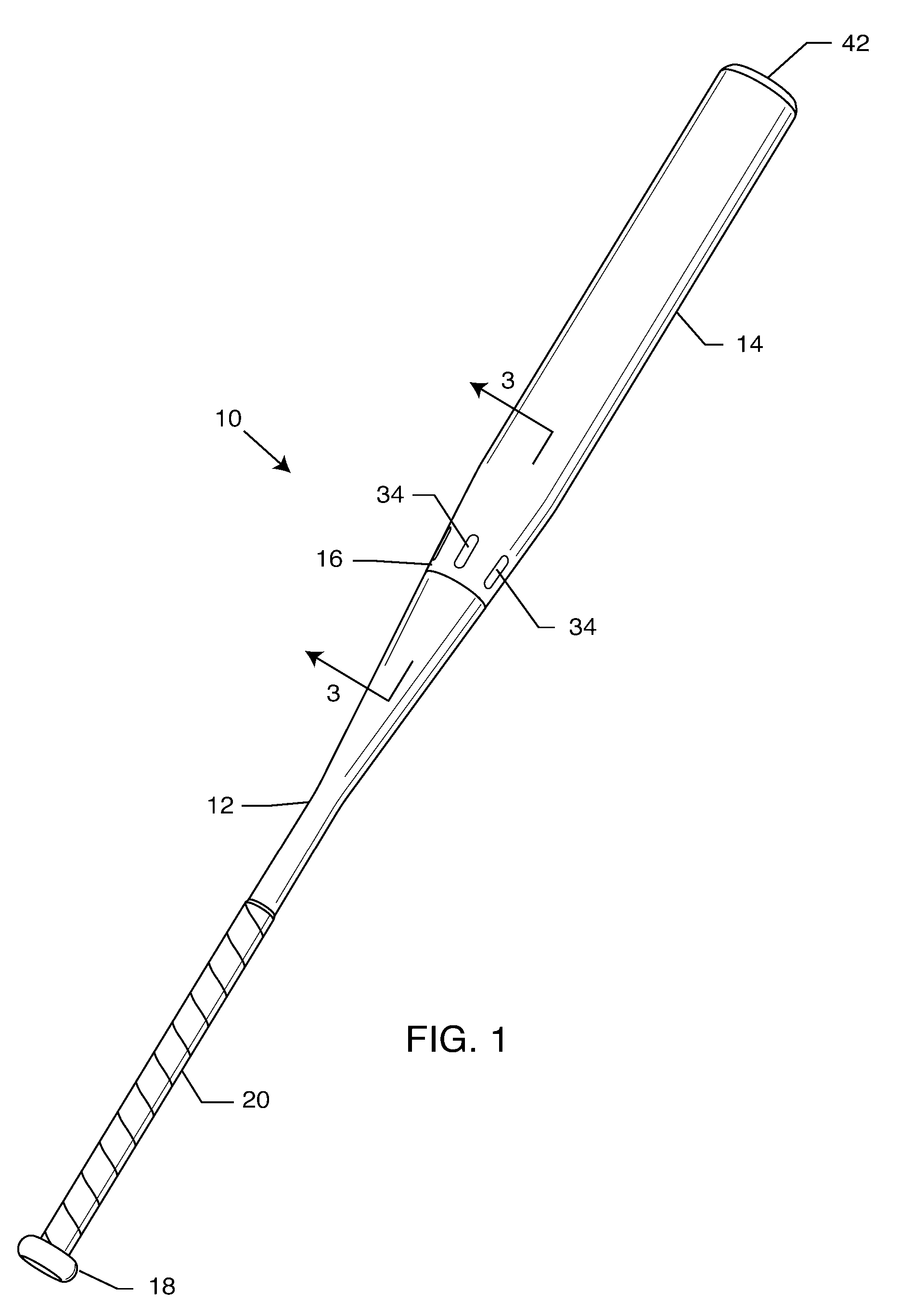
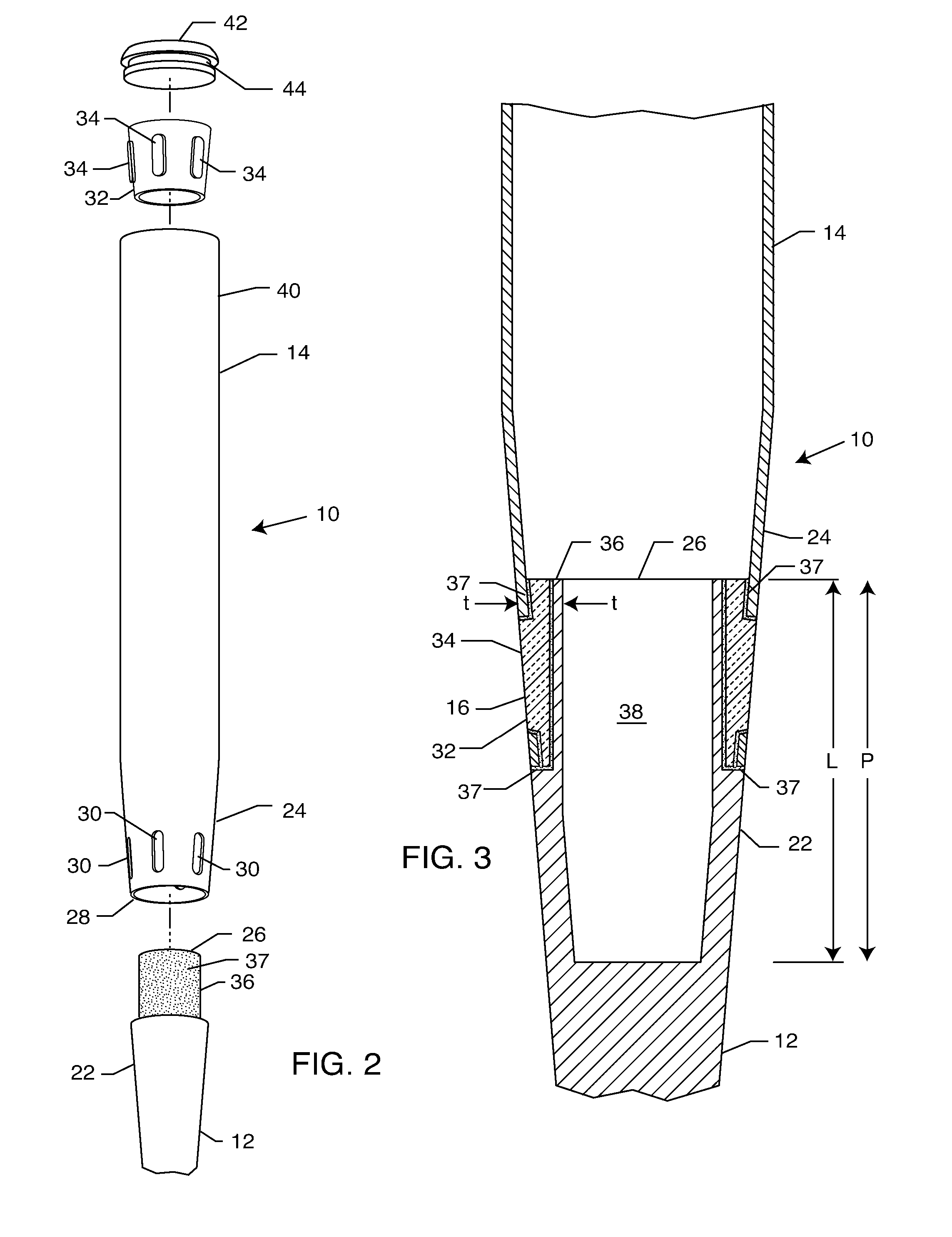
[0019] As shown in FIGS. 1-3 for purposes of illustration, the present invention is concerned with a multi-component bat 10 which has an elongate hollow handle shell portion 12, an elongate hollow barrel shell portion 14 and an intermediate cylindrically tapered section 16 interconnecting the handle portion 12 and the barrel portion 14. A knob 18 is securely attached to the end of the handle portion 12 by a variety of means, including, but not limited to, binding agents, glues, adhesives, or the like. The knob 18 may be made of various materials including, without limitation, aluminum, polyurethane, polycarbonate, a composite material, magnesium, Zytel, Delrin, plastic, or the like. Also, the handle portion 12 is typically wrapped with a grip 20 comprised of rubber, polyurethane, leather or the like, for comfort.

[0020] The handle and barrel portions 12, 14 may be made of various materials including, without limitation, wood, a lightweight yet durable metal (e.g., aluminum, titanium...


PUM


Abstract

A process for assembling a multi-component baseball bat includes providing a bat barrel having an end with a plurality of slots and selecting a bat handle. A section of the handle is enveloped by the end of the barrel. The barrel and handle are interconnected in coaxial engagement to define an intermediate tapered section which returns energy and power to the barrel that emanates from the barrel due to an impact of a ball on the barrel. An example of a multi-component baseball bat formed by the process includes a bat barrel having a plurality of slots; a bat handle; and a connector attached to an end of the handle. The connector engages the slots of the barrel and is coaxially disposed between the barrel and the handle for interconnecting the barrel and handle in an aligned relation, to return energy and power to the barrel.

Description

BACKGROUND OF THE INVENTION [0001] The present invention relates to baseball and softball bats. More particularly, the present invention relates to a multi-component bat and a related assembly process. [0002] Baseball and softball are very popular sports in the United States, Mexico, Cuba, Japan and elsewhere. Due to the competitive nature of the sports, players are constantly seeking ways of improving their performance. An important aspect of baseball and softball is the ability to effectively hit the ball. Aluminum (metal) bats are allowed in baseball amateur play from Little League to College levels. Metal bats are also typically used in slow and fast pitch softball. Such bats are advantageous over wood bats in that they do not break and splinter like wood bats and thus can be repeatedly used with consequent cost savings. Metal bats also have a larger optimal hitting area or power zone (commonly referred to as the β€œsweet spot”) than wood bats. Furthermore, the ball comes off a me...

Claims


Application Information

Patent Timeline
06 Sep 2007
Publication
US20070207882A1
IPC
A63B59/00
CPC
A63B59/06; A63B2102/18; A63B59/50; A63B2102/182
Inventors
VAN NGUYEN, THU