Secondary dynamic balance checking structure and method used for DC motor

A DC motor and balancing technology, which is applied in the field of vibration reduction and noise reduction, can solve the problems of increased difficulty in reaching the standard and poor dynamic balance effect, and achieve the effects of improving performance, meeting structural vibration acceleration requirements, and improving dynamic balance accuracy

Inactive Publication Date: 2011-08-17
SHANGHAI NANYANG ELECTRICAL MACHINERY
View PDF4 Cites 0 Cited by
  • Summary
  • Abstract
  • Description
  • Claims
  • Application Information

AI Technical Summary

Problems solved by technology

In order to ensure its low noise and low vibration requirements, the motor with special requirements needs to meet the requirements of structural vibration acceleration indicators, and the dynamic balance accuracy requirements must reach G1 level. At this time, the balance weight must be installed in the corresponding In terms of position, due to the large amount of unbalance and other reasons, the effect of the first dynamic balance calibration may not be good, and the difficulty of reaching the standard will increase.

Method used


Image

  • Secondary dynamic balance checking structure and method used for DC motor
  • Secondary dynamic balance checking structure and method used for DC motor
  • Secondary dynamic balance checking structure and method used for DC motor

Examples


Embodiment Construction

[0016] The present invention will be further described below in conjunction with accompanying drawing.

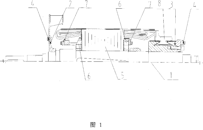
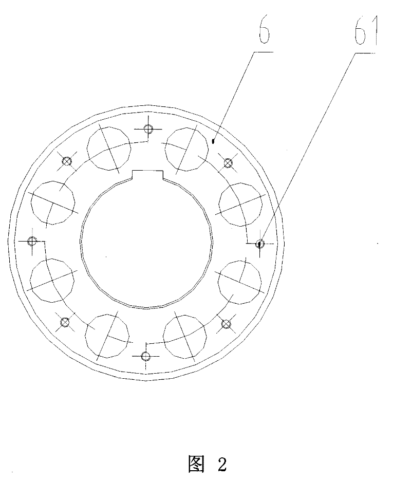
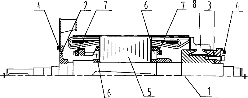
[0017] see figure 1 and figure 2 , the figure shows a kind of calibration dynamic balance structure for a DC motor of the present invention, including a motor body 1, on the balance seat 2 and the commutator pressure ring 3 at the two ends of the armature of the motor body 1, respectively The first balance weight 4 is installed, and there is an iron core pressure ring 6 at both ends of the iron core 5, and the second balance weight 7 installed on the two iron core pressure rings 6 respectively, and the end faces of the two iron core pressure rings 6 Several balance weight installation screw holes 61 are also provided to install the second balance weight 7 .

[0018] A secondary calibration dynamic balancing method for DC motors of the present invention comprises the following steps:

[0019] The first calibration and dynamic balancing step, that is, when the stacking o...


PUM


Abstract

The invention discloses a twice correction dynamical balance structure used for a DC electrical motor, comprising an electrical motor body, wherein, first balance weights are additionally installed on a balance bed and a commutator pressure ring at the two ends of an armature of the electrical motor body respectively, and magnet core pressure rings are respectively installed at the two ends of a magnet core; the balance structure also comprises second balance weights are respectively installed on the two magnet core pressure rings, and a plurality of balance weight installation screw holes are installed on the end surfaces of the two magnet core pressure rings so as to install the second balance weights. The method comprises the following steps: the first correction dynamical balance; inserting line and dipping lacquer; and the second correction dynamical balance. In the invention, the dynamical balance is pre-corrected on an armature core which is not inserted with the line, so as tofirst adjust the residual unbalance generated by the same plate difference of a stamped steel and the error caused by manufacturing and processing of a commutator on the magnet core to a certain precision required; the second correction balance is carried out after the line is inserted, thus being conducive to improving the dynamical balance precision of the whole DC electrical motor, and effectively reducing the vibration velocity and the noise of the electrical motor, and improving the performance of the electrical motor.

Description

technical field [0001] The invention relates to a vibration reduction and noise reduction technology for a DC motor, in particular to a secondary calibration dynamic balance structure and method for a DC motor. technical background [0002] Generally, after the armature wire embedding and varnish dipping are completed, the DC motor performs a dynamic balance calibration to ensure that the remaining unbalance of the armature meets a certain accuracy requirement, which can meet the vibration speed and noise index of the motor to meet the standard requirements, while some special DC The motor has higher requirements on vibration speed and noise index, and needs to meet the requirements of structural vibration acceleration index. The structural vibration acceleration index mainly depends on the size of the shaft frequency of the motor, and the size of the shaft frequency is affected by the accuracy of the dynamic balance of the armature. At this time, it may be difficult to adj...

Claims


Application Information

Patent Timeline
IPC IPC(8): H02K15/16G01M1/30
Inventor 徐立伟
Owner SHANGHAI NANYANG ELECTRICAL MACHINERY
Why Eureka
Try Eureka