Eureka AIR delivers breakthrough ideas for toughest innovation challenges, trusted by R&D personnel around the world.

Method for operating a parallel hybrid drive train of a vehicle

a hybrid drive and drive train technology, applied in hybrid vehicles, engine-driven generators, transportation and packaging, etc., can solve the problems of rotational speed value and assumption of undesirably high values

Inactive Publication Date: 2007-09-06
ZF FRIEDRICHSHAFEN AG
View PDF8 Cites 34 Cited by
  • Summary
  • Abstract
  • Description
  • Claims
  • Application Information

AI Technical Summary

Benefits of technology

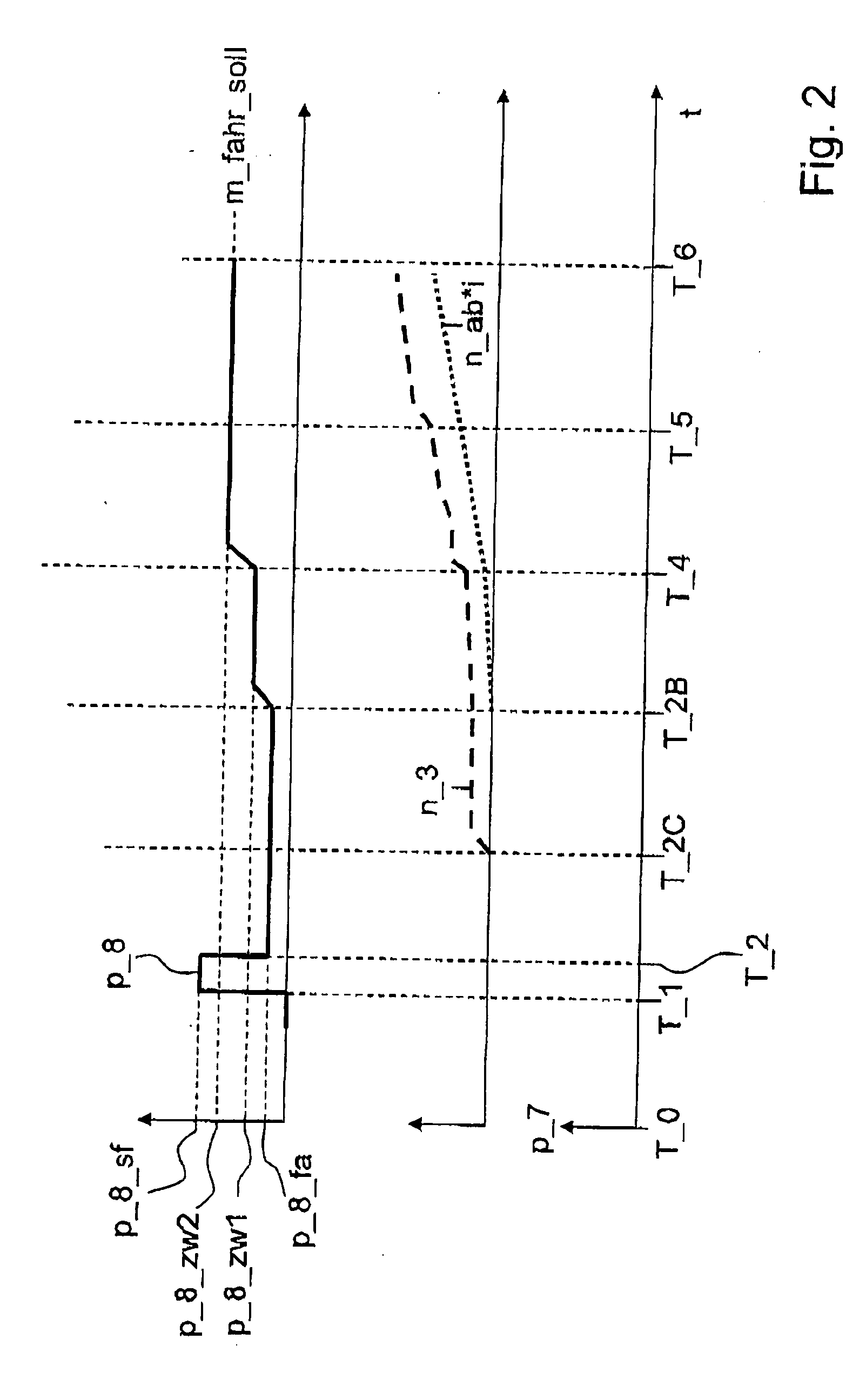
[0010] By the inventive procedure of regulatedly adjusting the driving rotational speed of the electric engine during the starting process of the internal combustion engine, it also is easily possible to adapt the driving rotational speed of the electric engine during the starting process of the internal combustion engine to changing operating states of the parallel hybrid drive train so that the shifting element between the electric engine and the output be permanently slip operated, it being possible by the regulation to reduce the slip on the shifting element to a required minimum so that the loads of the shifting element resulting from the slip operation be reduced in comparison with drive trains of hybrid vehicles already known from the prior art.

Problems solved by technology

However, it is here disadvantageous that the calculated rotational speed value, under operating conditions that change during the starting process of the internal combustion engine, is in circumstances too low and the shifting element is not slip operated over the whole starting process of the internal combustion engine.
It is further possible also that the rotational speed value of the rotational speed of the electric engine determined for the operating state existing at the calculation moment be basically too high for the operating states of the drive train that follow wherefore a load of the shifting element caused by the slip in the area of the shifting element assumes undesirably high values.

Method used


Image

  • Method for operating a parallel hybrid drive train of a vehicle
  • Method for operating a parallel hybrid drive train of a vehicle
  • Method for operating a parallel hybrid drive train of a vehicle

Examples


Embodiment Construction

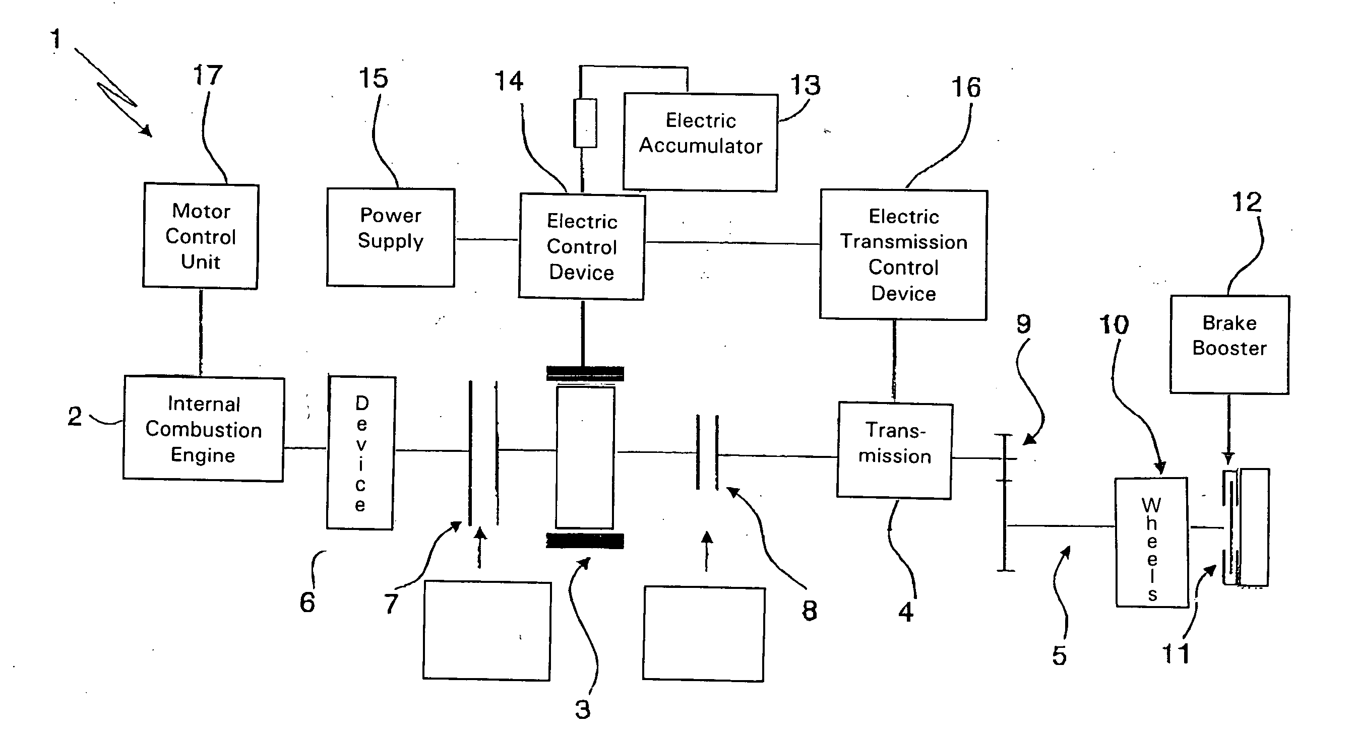
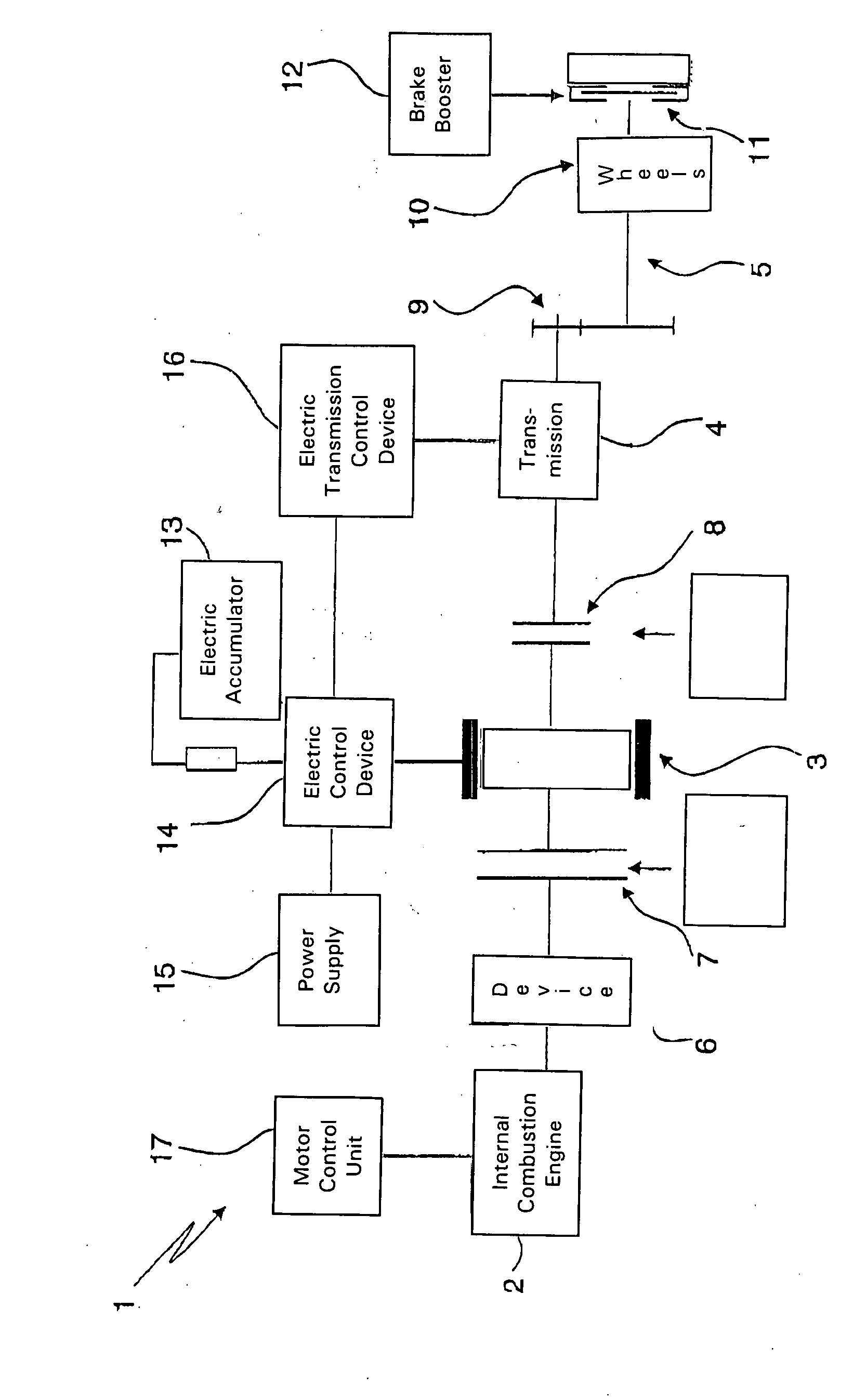
[0020]FIG. 1 shows a parallel hybrid drive train 1 of a vehicle in extensively schematic representation in the form of a block gearshift pattern. The parallel hybrid drive train 1 comprises an internal combustion engine 2, an electric engine 3, a transmission 4 and an output 5. Between the internal combustion engine 2 and the electric engine 3 are located a device 6 for damping rotational irregularities and a frictionally engaged shifting element 7.

[0021] By way of the shifting element 7, an operative connection can be created between the internal combustion engine 2 and the electric engine 3 in order to make possible producing different operating states of the parallel hybrid drive train 1 of the vehicle such as a drive exclusively via the electric engine 3, a parallel drive via the internal combustion engine 2 and the electric engine 3, or drive exclusively via the internal combustion engine 2.

[0022] By arranging the shifting element 7 between the internal combustion engine 2 an...


PUM


Abstract

A method is described for operating a parallel hybrid device train (1) of a vehicle having an internal combustion engine (2), an electric engine (3) and an output (5) wherein the electric engine (3) is disposed in the power train between the output (5) and the internal combustion engine (2) and both between the internal combustion engine (2) and the electric engine (3) and between the electric engine (3) and the output (5) is respectively provided a frictionally engaged shifting element (7, 8). In addition, a nominal output torque abutting on the output (5) can be adjusted according to the transmitting capacity of the first shifting element (8) located between the electric engine (3) and the output (5). According to the invention, the transmitting capacity of the first shifting element (8) is adjusted under control according to the nominal input torque required so that the first shifting element (8) has a transmitting capacity needed for producing the nominal output torque on the output (5). Furthermore, an input rotational speed of the electric engine (3) is adjusted under regulation during a starting process of the internal combustion engine (2) in order to keep the first shifting element in slip operation at least during the starting process of the internal combustion engine (2) and to produce the nominal output torque on the output (5).

Description

[0001] This application claims priority from German Application Serial No. 10 2006 005 468.7 filed Feb. 7, 2006. FIELD OF THE INVENTION [0002] The invention concerns a method for operating a parallel hybrid drive train of a vehicle. BACKGROUND OF THE INVENTION [0003] DE 10 2004 002 061 A1 has disclosed a method for control and regulation of a drive train of a hybrid vehicle and a drive train of a hybrid vehicle. With the method for control and regulation of a drive train of a hybrid vehicle having an internal combustion engine, an electric engine, a shifting element located between the electric engine and an output in a power flow of the drive train and a shifting element designed with continuously variable transmitting capacity and a clutch device situated between the electric engine and the internal combustion engine and by way of which the electric engine and the internal combustion engine can be brought to operative connection, a drive train of a hybrid vehicle be operable in a ...

Claims


Application Information

Patent Timeline
Patent Type & Authority Applications(United States)
IPC IPC(8): H02P15/00B60L50/16B60W30/18
CPCB60K6/48B60L2240/486B60W10/02B60W10/06B60W10/08Y10T477/32B60W30/18027B60W2710/105Y02T10/6221Y02T10/6286Y10T477/26B60W20/00Y02T10/62B60K2006/268B60W2510/105B60W10/26B60W2710/24
Inventor DREIBHOLZ, RALFKALTENBACH, JOHANNESGROMUS, MICHAELBLATTNER, STEFANALLGAIER, BERNDKILIAN, STEFANSCHIELE, PETERTENBROCK, FRIEDRICHFROTSCHER, GERD
Owner ZF FRIEDRICHSHAFEN AG
Why Eureka
Eureka Blog
Learn More