Self-cleaning and mixing microfluidic elements

a technology of microfluidic elements and self-cleaning, which is applied in the direction of electrostatic separators, electrolysis, isotope separation, etc., can solve the problems of low power requirements of systems, achieve easy measurement, low power requirements, and facilitate the effect of controlling device functionality

Active Publication Date: 2007-09-13
SYNVIVO INC
View PDF10 Cites 11 Cited by
  • Summary
  • Abstract
  • Description
  • Claims
  • Application Information

AI Technical Summary

Benefits of technology

[0020] The use of electrothermal flows in a microfluidic system offers several advantages and benefits. First, no moving parts are involved in such systems. Also, such systems have low power requirements. For example, an electrode voltage in the range of 1 Vrms and frequency of 106 Hz (of an AC field) is able to induce a flow field with maximum velocity of 100 μm/sec in microdevices. Electrothermal flow provides an ease of control. Process parameters that induce electrothermal flows are easier to measure. This allows the control of device f...

Problems solved by technology

Also, such systems h...

Method used


Image

  • Self-cleaning and mixing microfluidic elements
  • Self-cleaning and mixing microfluidic elements
  • Self-cleaning and mixing microfluidic elements

Examples


Embodiment Construction

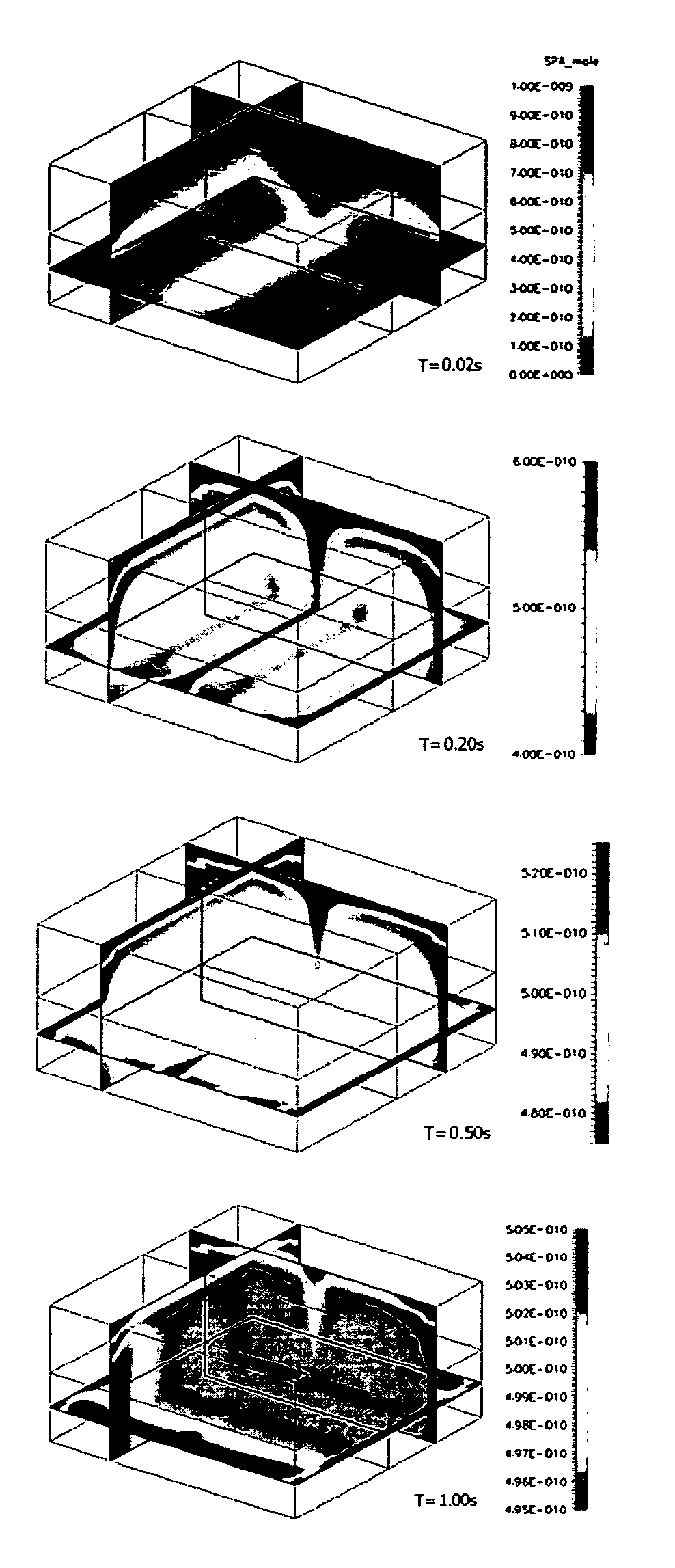
[0038] Traditionally, microdevices use electric fields (AC or DC) as a source of energy to induce flow of buffer using electroosmosis, transport and separation of samples using electrophoresis, or transport of particles using dielectrophoresis. In this context, the present invention focuses on the use of an electric field to facilitate the transport and mixing of two or more analytes or liquid streams, as well as cleaning (removal of particles or analytes) of devices using electrothermally induced fluid flow.

[0039] Electrothermally Induced Fluid Flow

[0040] When an electric field is applied to a buffer, it induces a temperature gradient in the buffer solution due to Joule heating. This, in turn, induces variations (non-uniformities) in the dielectric property of the buffer. The non-uniformity in the dielectric property results in a body force being exerted on the liquid and, consequently, a flow motion is observed. The present invention utilizes this electrothermally induced flow m...


PUM

PropertyMeasurementUnit
Angleaaaaaaaaaa
Angleaaaaaaaaaa
Temperatureaaaaaaaaaa

Abstract

Apparatus and methods are disclosed for mixing and self-cleaning elements in microfluidic systems based on electrothermally induced fluid flow. The apparatus and methods provide for the control of fluid flow in and between components in a microfluidic system to cause the removal of unwanted liquids and particulates or mixing of liquids. The geometry and position of electrodes is adjusted to generate a temperature gradient in the liquid, thereby causing a non-uniform distribution of dielectric properties within the liquid. The dielectric non-uniformity produces a body force and flow in the solution, which is controlled by element and electrode geometries, electrode placement, and the frequency and waveform of the applied voltage.

Description

CROSS-REFERENCE TO RELATED APPLICATIONS [0001] This Application is a Continuation In Part of application Ser. No. 10 / 307,907, filed 02 Dec. 2002.STATEMENT REGARDING FEDERALLY SPONSORED RESEARCH OR DEVELOPMENT [0002] The U.S. Government may have certain rights in this invention pursuant to SBIR Contract Number W81XWH06C0067 awarded by the United States ArmyINCORPORATED-BY-REFERENCE OF MATERIAL SUBMITTED ON A COMPACT DISC [0003] Not Applicable BACKGROUND OF THE INVENTION [0004] 1. Field of the Invention [0005] The present invention relates generally to devices and methods used for mixing and cleaning in microfluidic systems. More particularly, this invention pertains to self-cleaning elements and mixing elements for use in microfluidic systems such as lab-on-a-chip and BIOMEMS systems. [0006] 2. Description of Related Art [0007] Miniaturized bioanalytical, lab-on-a-chip, integrated microfluidic and Bio-Micro Electro Mechanical Systems (“BioMEMS”) (hereafter collectively referred as mi...

Claims


Application Information

Patent Timeline
IPC IPC(8): B01D57/02B03C5/00
CPCB01F13/0079B01F13/0081B01L3/5027B01L2300/1833B01L2400/0415B01L2400/0442Y10S366/04B08B7/0064B08B9/00F04B19/006F04B19/24B01L99/00B01L2400/0493B01L13/02Y10T137/0391Y10T137/034Y10T137/0329B01F33/3033B01F33/3034
Inventor KRISHNAMOORTHY, SIVARAMAKRISHNANFENG, JIANJUN
Owner SYNVIVO INC
Why Eureka
Try Eureka