Apparatus and method for laser welding

a technology of apparatus and laser welding, applied in metal working apparatus, welding/soldering/cutting articles, manufacturing tools, etc., can solve the problem of needing to remove the smell of the apparatus

Active Publication Date: 2007-09-13
NISSAN MOTOR CO LTD
View PDF15 Cites 36 Cited by
  • Summary
  • Abstract
  • Description
  • Claims
  • Application Information

AI Technical Summary

Problems solved by technology

Such a fume needs to be removed since it destabilizes the amount of heat that the laser beam applies to the work piece.

Method used


Image

  • Apparatus and method for laser welding
  • Apparatus and method for laser welding
  • Apparatus and method for laser welding

Examples


first embodiment

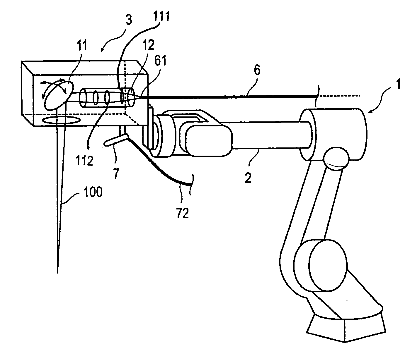
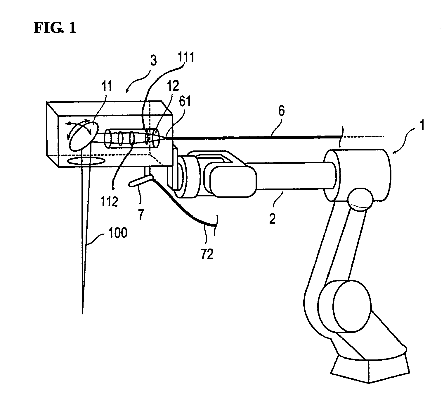
[0060]The jetting directions of air of the air injecting nozzles 81 and 82 can correspond to directions transverse to the laser beam, as described above in relation to the first described embodiment. As shown, it is configured that the laser irradiating point P is not included within the injection range of air. The other features are similar to those of the Thus, their explanations are omitted.

second embodiment

[0061]FIG. 7 is a diagram illustrating the operation of air injection according to the Because FIG. 7 is provided to illustrate the operation of air injection, each component is expressed in a simplified manner.

[0062]The disclosed system is configured such that it can move the laser irradiating point P by moving the laser processing head 3 using the robot 1 or by moving the reflecting mirror 11. Therefore, in the second embodiment, the switching valve 85 is switched in order to inject the air opposite to the direction of moving the laser irradiating point P. In other words, when moving the laser irradiating point P in the direction indicated by the arrow “a”, the switching valve 85 is switched in order to inject the air from the air injecting nozzle 81. When moving the laser irradiating point P in the direction indicated by the arrow “b”, the switching valve 85 is switched in order to inject the air from the air injecting nozzle 82.

[0063]By doing so, the fume H produced from the wo...

third embodiment

[0067]FIGS. 8a and 8b are diagrams illustrating the operation of the system constructed in accordance with the FIG. 8a is a side view, and FIG. 8b is a diagram of a laser outlet. Each component in FIGS. 8a and 8b is expressed in a simplified manner.

[0068]In this third embodiment, the installation positions of the air injecting nozzles 81 and 82 are set such that the air injecting positions are spaced away from each other by an offset width T, and the air is injected from both the air injecting positions during welding as shown in FIG. 8b. For this reason, the switching valve 85 is not required. The air injected from the air injecting nozzles 81 and 82 produce a vortex as shown in FIG. 8b. Such a vortex serves to blow out the air by centrifugal force. Therefore, it is possible to blow out the created fume by using the vortex.

[0069]FIG. 9 is a schematic diagram illustrating a system constructed in accordance with a fourth embodiment of the invention. FIG. 10 is a schematic diagram of...


PUM

PropertyMeasurementUnit
diameteraaaaaaaaaa
diameteraaaaaaaaaa
distanceaaaaaaaaaa

Abstract

A laser welding apparatus and method reduce the effect of the fume resulting from a weld. An air injecting nozzle is installed at a laser processing head. The injecting direction of air from the air injecting nozzle is set such that the air flows across a laser beam irradiated from the laser processing head while the air flow avoids direct contact with the laser irradiating point on the work piece.

Description

CROSS-REFERENCE TO RELATED APPLICATION[0001]This application claims priority from Japanese Patent Application Serial No. 2006-064743, filed Mar. 9, 2006, and No. 2006-331021, filed Dec. 7, 2006, each of which is incorporated herein in its entirety by reference.TECHNICAL FIELD[0002]The invention relates in general to an apparatus and method for conducting laser welding.BACKGROUND[0003]Laser welding is currently used to carry out robotic welding. Japanese Patent No. 3229834 discloses an example of such a welding technique, wherein a laser welding apparatus is installed at a tip of a robotic arm for irradiating a laser beam. The laser welding apparatus is configured to move away from a welding point and rotate a reflecting mirror located within the laser welding apparatus, thereby irradiating the laser beam at a predetermined welding point. Such type of welding is referred to as remote welding.[0004]However, in laser welding, a gas with eluted metal is produced from a portion of a work...

Claims


Application Information

Patent Timeline
Patent Type & Authority Applications(United States)
IPC IPC(8): B23K26/20B23K26/14B23K26/142B23K26/21
CPCB23K26/0807B23K26/0884B23K26/3293B23K26/147B23K26/1405B23K26/082B23K26/142B23K2101/34B23K2103/08
Inventor SAKAMOTO, TSUYOSHIOKADA, KAZUYAMORIKAWA, YASUSHIHASEGAWA, TAKAHISASAITO, ATSUSHIYAMASHITA, JUNICHI
Owner NISSAN MOTOR CO LTD
Why Eureka
Try Eureka