Gas cooker appliance with an orientable control panel

a technology of orientable control panel and gas cooker, which is applied in the direction of electric heating, domestic heating, lighting and heating apparatus, etc., can solve the problems of low height, inconvenient operation of control knobs by users, and the effect of dirt entry and spillage on the cooking surfa

Inactive Publication Date: 2007-09-13
COPRECITEC
View PDF11 Cites 40 Cited by
  • Summary
  • Abstract
  • Description
  • Claims
  • Application Information

AI Technical Summary

Benefits of technology

[0005]On the cooker appliance of the invention an orientable control panel is achieved which provides a greater height for the panel knobs and a vertical arrangement of the rotary knob shafts, ther...

Problems solved by technology

Cooker appliances whose control panel is situated during cooking on a horizontal plane adjacent to the cooking surface or working plane have the drawback of being exposed to the entry of dirt and ...

Method used


Image

  • Gas cooker appliance with an orientable control panel
  • Gas cooker appliance with an orientable control panel

Examples


Embodiment Construction

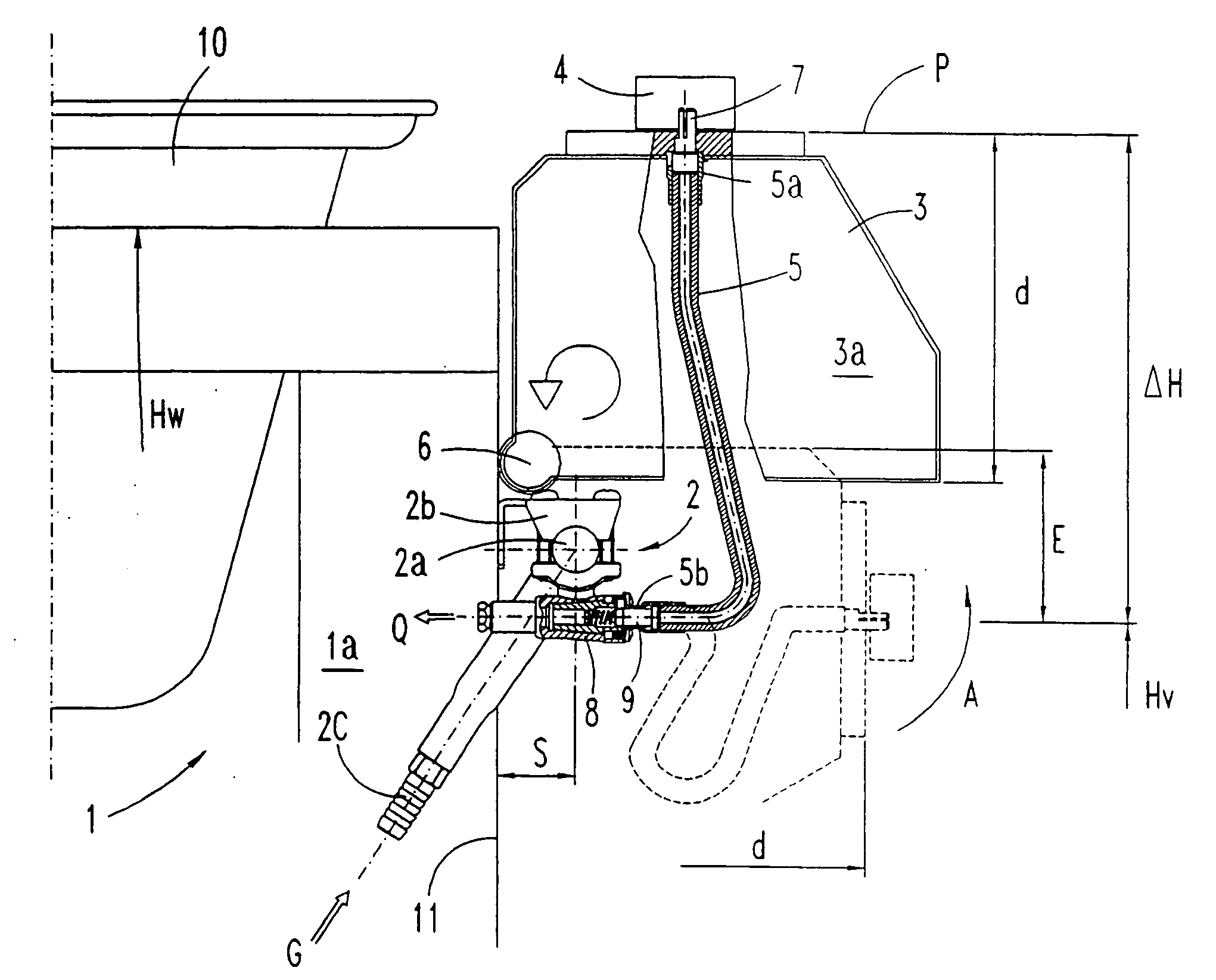
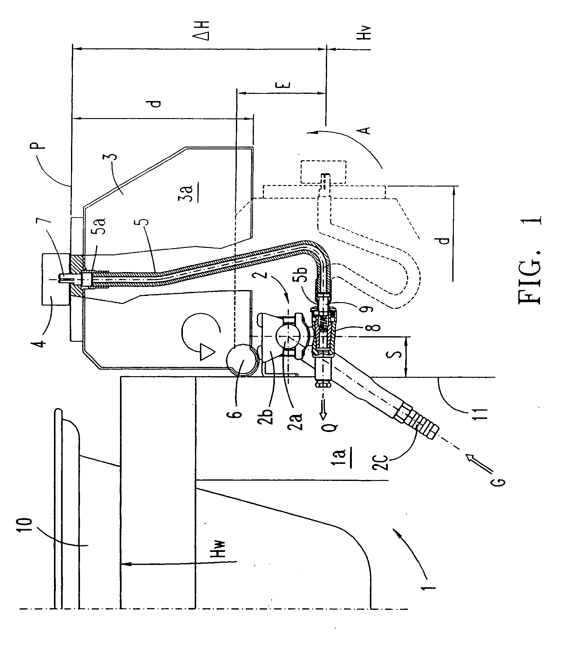
[0007]In reference to FIG. 1, a preferred embodiment of the cooker appliance 1 comprises an appliance frame la formed of a cooking surface or plane 10 of working height Hw, for instance an uncovered grill plate, and various support walls, a front gas manifold assembly 2 fixed to an installation support wall 11 on the frame by means of a mounting bracket 2b, and a control panel 3 provided with a number of rotary knobs 4 for regulating the gas flow “Q”.

[0008]The gas manifold assembly 2 comprises a conduit 2a for distributing the gaseous fuel “G” of the cooker appliance 1, a plurality of taps 3 mounted apart from one another and in a fixed position in relation to said front mounting panel 1, and a cooker gaseous fuel “G” supply nipple. Each of the gas taps 8 is provided with a rotary shaft 9 for regulating a flow “Q” supplied by each tap to the cooking surface 10, oriented horizontally towards the exterior of the appliance, and positioned at a height “Hv” of the frame 1a below the cook...


PUM


Abstract

The cooker appliance (1) has a horizontal cooking surface (10) of a given height (Hw), a gas “G” manifold assembly (2) with a plurality of taps (8) provided with a rotary shaft (9) for regulating the gas flow (Q), supported in a fixed position apart from one another on a front support wall (11) and at a given height (Hv) of the appliance. The control panel (3) provided with each of the rotary tap control knobs (4) is orientable up to as much as a right angle (A) by means of a pivoting axle (6), whereby the control knobs (4) are positioned either downwards in a rest position or else upwards at the level of the cooking plane (10) for the regulating manoeuvre, on a horizontal plane (P) at an increased height “Hv+Hv”. The control knob shafts (7) are coupled to the taps (8) by means of a flexible shaft (5) for transmitting the respective rotation, extended within a cavity (3a) for housing the taps (8) which is formed by the control panel.

Description

TECHNICAL FIELD[0001]The present invention relates to an arrangement of the panel for the control of the gaseous fuel on a household cooker appliance.PRIOR ART[0002]Gas cooker appliances are already known that are provided with a gas distributing conduit with a number of regulating taps fixed to the frame of the appliance and a control panel fixed to an outer support wall on the appliance, at a height from the floor suitable for operating the control knobs. Likewise known is a cooker appliance provided with a gaseous fuel manifold assembly fixed to the frame of the appliance, wherein each tap is set apart from its respective control knob. On these cooker appliances each of the knobs has a rotary shaft coupled to a means for transmission of the rotation for regulating the gas flow supplied by the respective tap. Said transmission means is a shaft of variable length but articulated and rigid, since the control panel is fixed and always remains in the same position relative to each tap...

Claims


Application Information

Patent Timeline
IPC IPC(8): H05B1/02
CPCF24C3/124
Inventor ALBIZURI, INIGO
Owner COPRECITEC
Why Eureka
Try Eureka