Method and Device for Reinforcing a Hollow Section with a Sealed Periphery

Inactive Publication Date: 2007-09-13
DAIMLER AG
View PDF1 Cites 5 Cited by
  • Summary
  • Abstract
  • Description
  • Claims
  • Application Information

AI Technical Summary

Benefits of technology

[0007] In a further, especially preferred configuration of the device according to the invention, the press-joining device contains a joining punch which is movably guided in a passage of the perforating punch, said passage opening out at the cutout at the end face. Furthermore, the press-joining device contains a die which is formed with a recess and bears against the outside of the hollow section, the recess having undercut contours and being in alignment with the passage of the joining punch. Due to the step of integrating the joining punch in the perforating punch, not only construction space but also a further work station are saved. Associated therewith, the process time for producing and for reinforcing the hollow section having a closed periphery is considerably reduced, since the transfer path into the joining station otherwise necessary is dispensed with. Furthermore, production tolerances which arise during the transfer from one work station to the other are prevented. Furthermore, the wall strip of the wall piece remains exactly positioned for the press-joining method, since the perforating punch holds the wall strip on the hollow section wall during the entire press-joining method.
[0008] A further preferred configuration of the device according to the invention relates to the integration of the perforating punch in an internal high pressure forming tool, in the impression of which the hollow section is accommodated. As a result, the reinforcing component can already be produced during the shaping of the hollow section by means of internal high pressure by virtue of the fact that the perforating punch cuts out the wall piece in the hollow section body being shaped or already finish-formed, in which case sufficiently sound sealing of the perforating punch in the opening must be assumed so that a pressure drop does not occur which would disturb the process for shaping the hollow section and would no longer provide for conformity to contour of the hollow section during a plurality of successive perforations for producing a plurality of spaced-apart reinforcing components. With the integration of the perforating punch and thus the production of the reinforcing component in the internal high pressure forming tool, the entire process for producing the hollow section is simplified in such a way as to save construction space and the production time is reduced. Relatively sharp-edged transitions between the hollow section and the reinforcing component bent into the hollow section interior can be produced by the internal high pressure, a factor which, depending on the intended use, may be necessary for optical reasons for as highly precise an outer contour of the hollow section as possible.
[0009] In a further, especially preferred configuration of the invention, the hollow section is formed by internal high pressure, wherein, following the forming in the internal high pressure tool, the opening is formed at existing internal high pressure, the wall piece is bent into the hollow section, and the wall strip is bent over and press-joined to the opposite hollow section wall. To this end, the press-joining device is integrated in the internal high pressure forming tool. As an addition to the above embodiments, the wall strip of the cut-out wall piece is also bent over and press-joined to the hollow section wall, so that the coupling of the production of the hollow section with the forming and fastening of the reinforcing component on the hollow section firstly provides for a highly compact type of construction of the device and minimizes the process time of the method for reinforcing the hollow section and for forming the hollow section.

Problems solved by technology

The known method involves some effort.
Furthermore, to carry out the joining, joining methods may also be used which would not have been advisable with the reinforcing component only in abutting contact with the hollow section wall on account of a lack of functionality.
As a result, the reinforcing component can already be produced during the shaping of the hollow section by means of internal high pressure by virtue of the fact that the perforating punch cuts out the wall piece in the hollow section body being shaped or already finish-formed, in which case sufficiently sound sealing of the perforating punch in the opening must be assumed so that a pressure drop does not occur which would disturb the process for shaping the hollow section and would no longer provide for conformity to contour of the hollow section during a plurality of successive perforations for producing a plurality of spaced-apart reinforcing components.

Method used


Image

  • Method and Device for Reinforcing a Hollow Section with a Sealed Periphery
  • Method and Device for Reinforcing a Hollow Section with a Sealed Periphery
  • Method and Device for Reinforcing a Hollow Section with a Sealed Periphery

Examples


Embodiment Construction

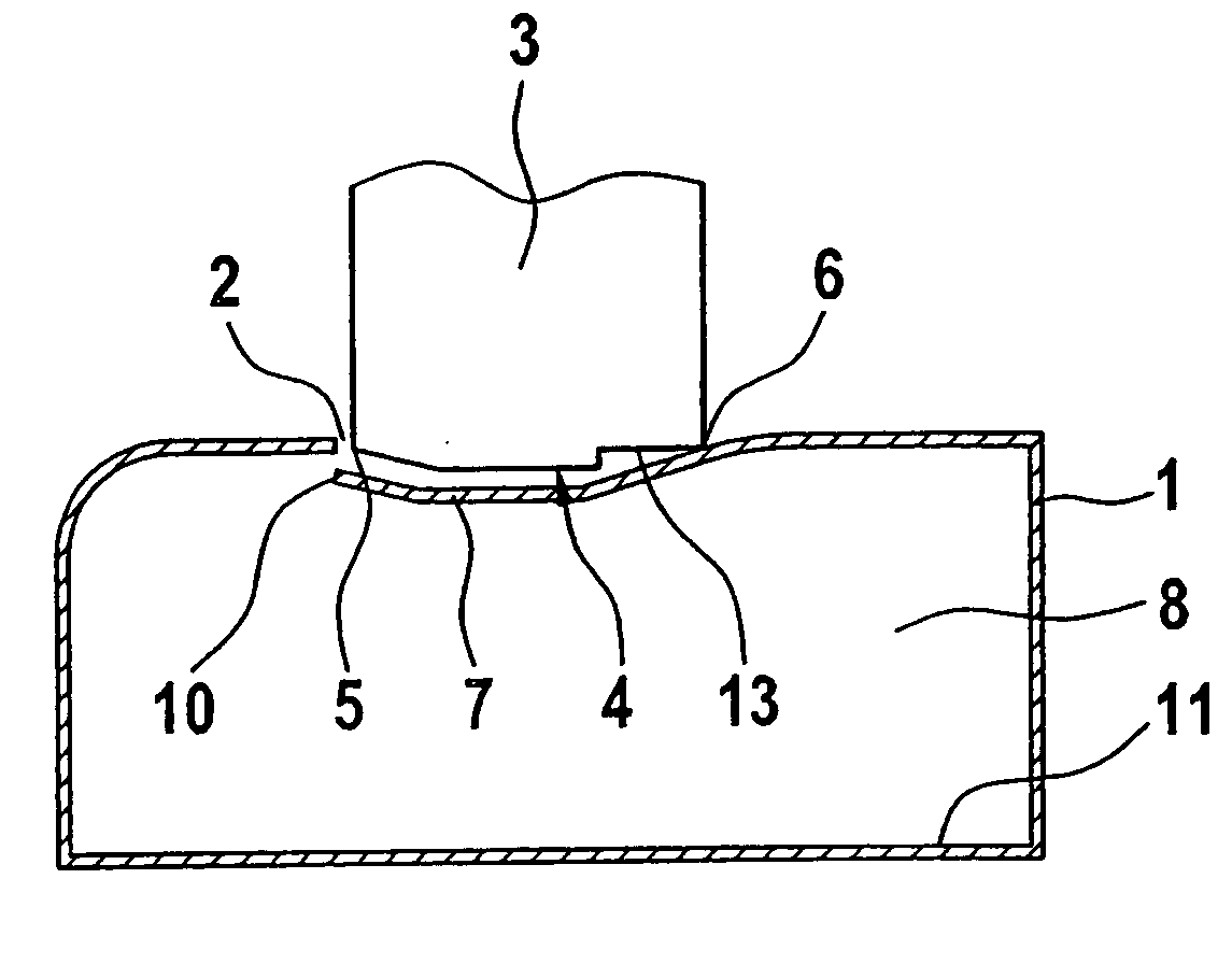
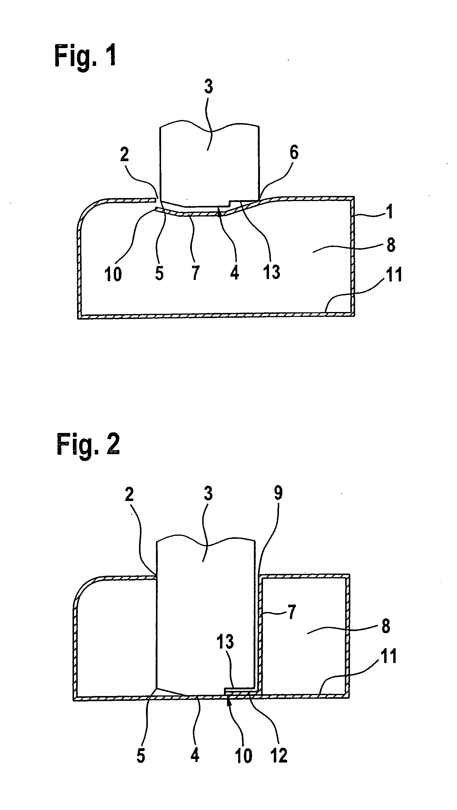
[0021] A hollow section 1 which has a closed periphery and is to be locally reinforced is shown in FIG. 1. To this end, a tool is used, by means of which an opening 2 is formed on the periphery of the hollow section. The tool may be a jet cutter, such as a laser cutting apparatus for example, but is formed here by a perforating punch 3, which is directed from outside onto the hollow section 1. At the end face 4 of the perforating punch 3, a cutting edge 5 is arranged around part of the periphery, whereas the rest of the periphery of the end face 4 of the punch 3 has a bending contour 6. In FIG. 1, a wall piece 7 which is to form the reinforcing component is cut out of the hollow section by the perforating punch 3, except for a narrow bendable peripheral region. In the present exemplary embodiment, the wall piece 7 has oversize with regard to its length, relative to the width of the hollow section 1.

[0022] After the wall piece 7 has been cut out, the perforating punch is moved still...


PUM

PropertyMeasurementUnit
Lengthaaaaaaaaaa
Pressureaaaaaaaaaa
Widthaaaaaaaaaa

Abstract

The invention relates to a method and a device for reinforcing a hollow section (1, 24) having a closed periphery, an opening (2) being produced at its periphery, after which a reinforcing component introduced into the hollow section interior (8, 25) is joined to the hollow section wall (11, 27) opposite the opening (2). In order to reinforce the hollow section (1, 24) as easily as possible, it is proposed that, at the location of the opening (2) to be produced, a wall piece (7, 23), forming the reinforcing component, of the hollow section (1, 24) be cut out except for a peripheral region, that the wall piece (7, 32) hanging in one piece on the opening edge (9) be bent into the hollow section (1, 24), with the opening (2) being formed. The length of the wall piece (7, 23) is dimensioned relative to the width of the hollow section (1, 24) in such a way that the wall piece (7, 23), with its free end (10, 26), at least comes into contact with the opposite hollow section wall (11, 27), and the free end (10, 26) is then joined to the hollow section wall (11, 27).

Description

BACKGROUND AND SUMMARY OF THE INVENTION [0001] This invention relates to a method of reinforcing a hollow section having a closed periphery. [0002] A method or device of this general type is known from German document DE 100 29 467 C1. In the known method, an opening is created on a finish-formed hollow section, after which a reinforcing component is introduced into the hollow section interior through the opening produced. The reinforcing component is then welded to the opening edge on the one hand and to the hollow section wall opposite the opening on the other hand. The known method involves some effort. Thus, the reinforcing component must be aligned exactly relative to the hollow section, then inserted and held in its position during the joining operation. [0003] The object of the invention is to develop a method of the type mentioned in which the hollow section is reinforced as easily as possible. Furthermore, a device with which the reinforcement is achieved is to be shown. Th...

Claims


Application Information

Patent Timeline
IPC IPC(8): B60R19/18B21D26/035B21D28/28B21D49/00
CPCB21D26/035B21D49/005B21D39/031B21D28/28
Inventor KOELLN, JOERGSCHULT, JENS
Owner DAIMLER AG
Why Eureka
Try Eureka