Electric machine with improved water cooling system

a technology of water cooling system and electric machine, which is applied in the direction of dynamo-electric machines, electrical apparatus, supports/enclosements/casings, etc., can solve the problems of extremely deficient heat transfer from the heat sources of electrical machines to the cooling collars, and the production of these cooling collars is very complex, so as to achieve positive effect on the utilization of electrical machines and high pressur

Active Publication Date: 2007-09-13
SIEMENS AG
View PDF10 Cites 35 Cited by
  • Summary
  • Abstract
  • Description
  • Claims
  • Application Information

AI Technical Summary

Benefits of technology

[0006] Accordingly, the invention is based on the object of providing an electrical machine having liquid cooling which provides sufficient cooling in a simple manner given simple fitting of the individual parts.
[0007] In addition, the intention is to provide reliable sealing of the cooling cycle.
[0009] Owing to the inventive design of the two bearing plates, a coolant flow is passed in the form of a coil or in meandering fashion around the stator, the number of sealing points to adjoining components being minimized. The comparatively effective thermal coupling to the stator results in an increase in the utilization of the electrical machine.
[0010] According to the invention, there is a reduction in the components of the housing, and no deflecting plates are required, as well as additional cooling coils or cooling collars. The fitting time for the electrical machine according to the invention is reduced owing to the omission of the comparatively complex surface sealing means, the fitting of the housing and possibly the cooling coils or cooling collars.
[0012] Owing to the reduction in the sealing points and the changeover associated therewith from surface sealing to radially sealing O rings, higher pressures are possible in the cooling cycle, which in turn has a positive effect on the utilization of the electrical machine.
[0013] Owing to the design of the outer contour of the electrical machine as a cross profile, the comer regions are free, with the result that free access to fixing screws on the flange is possible from the rear of the electrical machine. A realization of round or octagonal outer contours is also possible, which likewise allow access to the fixing screws on the flange.

Problems solved by technology

The production of these cooling collars is very complex; the heat transfer from the heat sources of the electrical machine to the cooling collars is likewise extremely deficient.

Method used


Image

  • Electric machine with improved water cooling system
  • Electric machine with improved water cooling system
  • Electric machine with improved water cooling system

Examples


Embodiment Construction

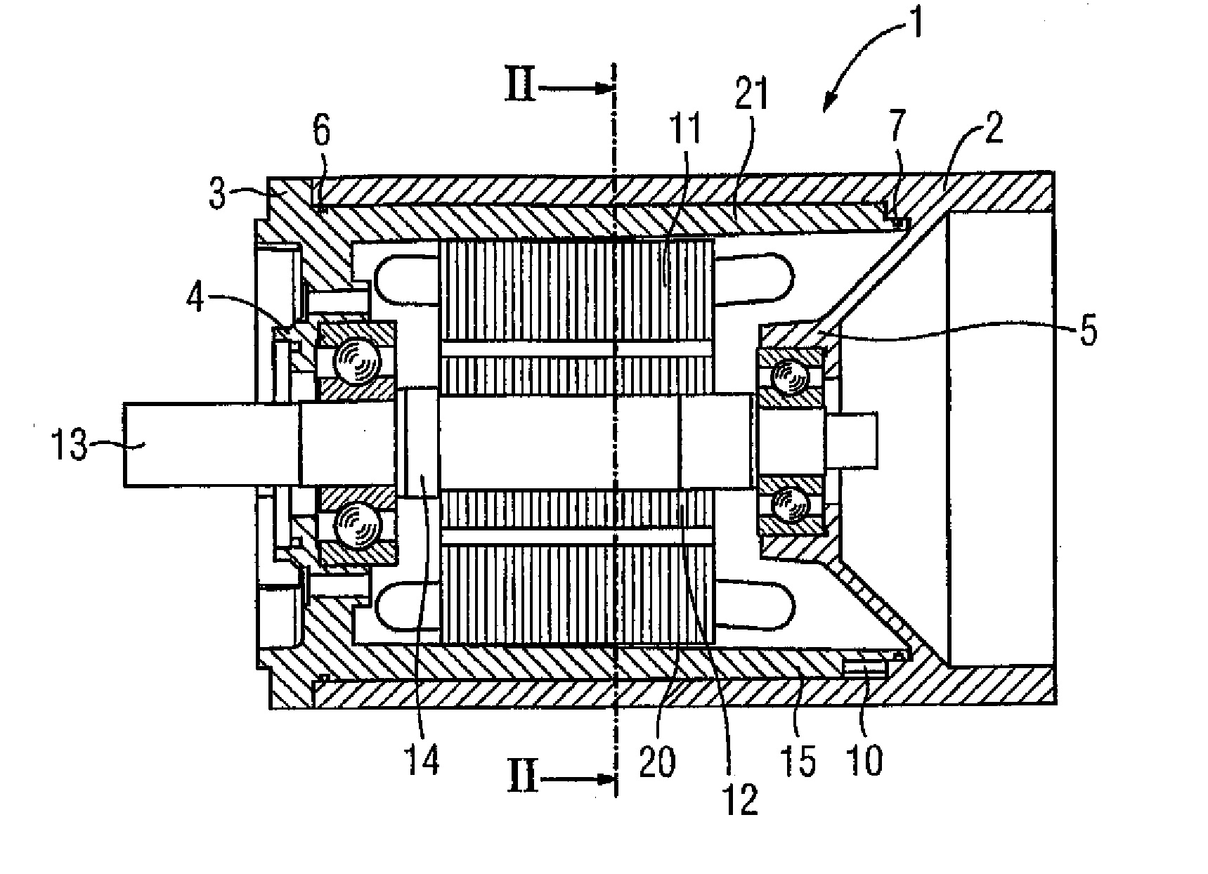
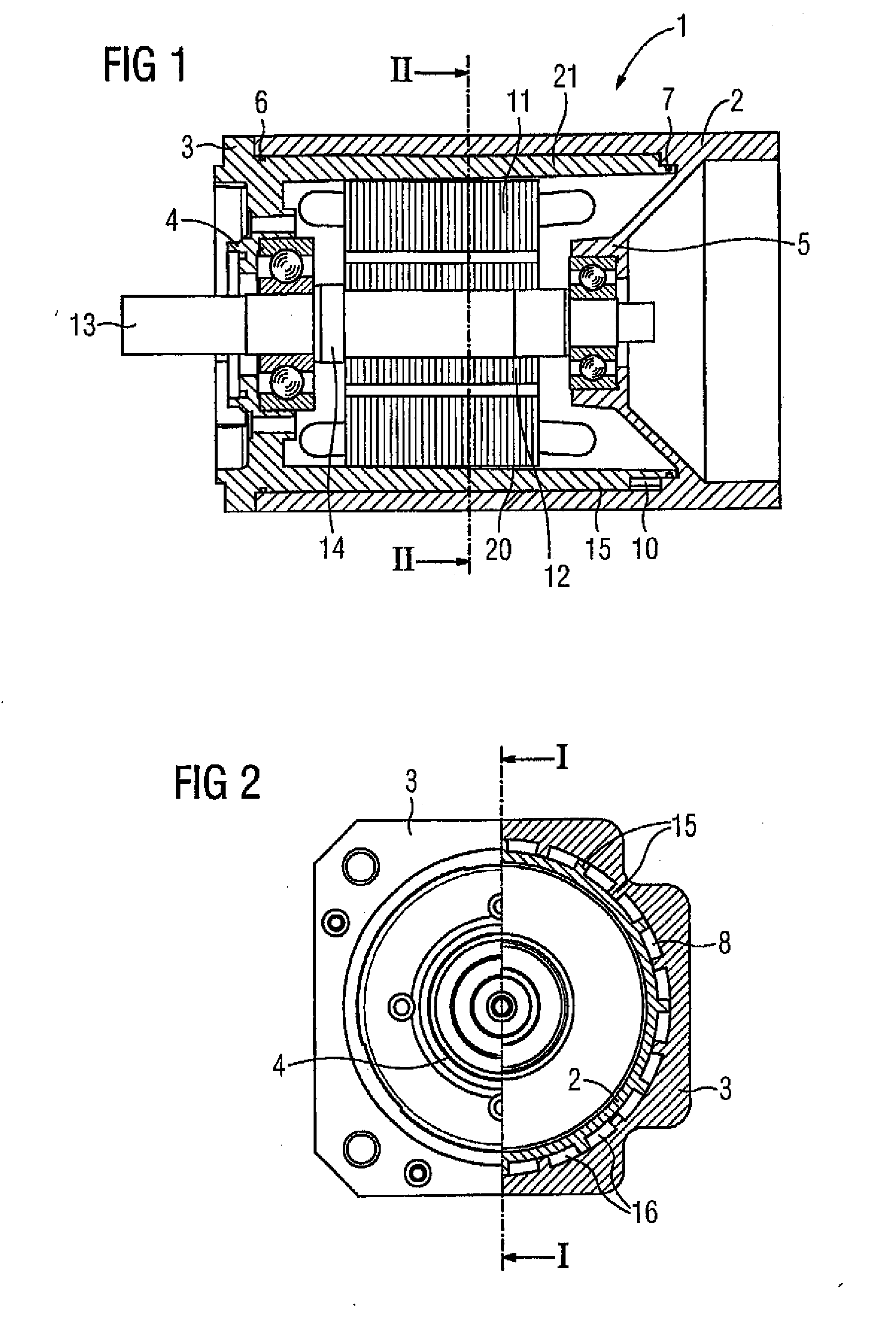
[0019]FIG. 1 shows, in a longitudinal section, a housing 1 according to the invention of an electrical machine having a stator 11 and a rotor 12. Two housing parts 2 and 3, which are pushed one inside the other in the manner of a tube, form the housing 1. Each housing part 2, 3 has in each case one bearing plate 5, 4, into which a bearing 9 is inserted and can be positioned by means of, for example, a collar 14. In this case, the collar 14 is preferably part of a shaft 13, but can also be fitted to the shaft 13 as an additional part. The shaft 13 bears a rotor 12. The housing part 2, 3 and the respective bearing plate 4, 5 preferably each have an integral design.

[0020] The sealing points provided between the housing parts 2 and 3 in the pushed-together state are sealed via O rings 6 and 7. The tube of the respective housing part 2, 3 extends axially over the stator 11, preferably even far over the respective end windings 15. In order to make it easier to fit the stator 11, the hous...


PUM


Abstract

The aim of the invention is to provide a fluid-cooled electric machine in a simple manner. To achieve this, a housing (1) is configured in two parts, in such a way that each housing part (2, 3) comprises a bearing bracket (4, 5) and said housing parts are designed (2, 3) to form cooling channels once assembled.

Description

BACKGROUND OF THE INVENTION [0001] The invention relates to an electrical machine, which has a housing, which has a stator with laminate layers, a rotor, whose shaft is mounted such that it can rotate via bearings positioned in bearing plates, and a liquid casing in the housing having meandering cooling channels. [0002] In order to increase the power and torque, the principle of liquid or water cooling is used in electrical machines. In liquid-cooled electrical machines, in this case different principles of liquid cooling are used. The liquid permeates an extruded profile which is equipped with axial cooling channels, usually in the corner regions. The deflection of the liquid flow takes place in the separate bearing plates or by means of additional deflecting plates, which are fitted on the outside on the electrical machine. [0003] Deflection in the bearing plates takes place by means of cast-in or drilled channels, and some of the tubes are also cast into the castings at the same ...

Claims


Application Information

Patent Timeline
Patent Type & Authority Applications(United States)
IPC IPC(8): H02K9/20H02K5/00H02K9/00H02K5/20
CPCH02K5/20H02K5/203
Inventor BAHR, HUBERTUSZISLER, MICHAEL
Owner SIEMENS AG
Why Eureka
Try Eureka