
Ultraviolet laser system and method having wavelength in the 200-nm range

a laser system and ultra-violet technology, applied in the direction of laser details, instruments, electrical equipment, etc., can solve the problems of inconvenient scanning application, inconvenient laser generation, and insufficient laser sources for semiconductor inspection at these wavelengths, and achieve high-efficiency conversion, inexpensive and highly efficient generation

Inactive Publication Date: 2007-09-13
LOCKHEED MARTIN CORP
View PDF21 Cites 43 Cited by
  • Summary
  • Abstract
  • Description
  • Claims
  • Application Information

AI Technical Summary

Benefits of technology

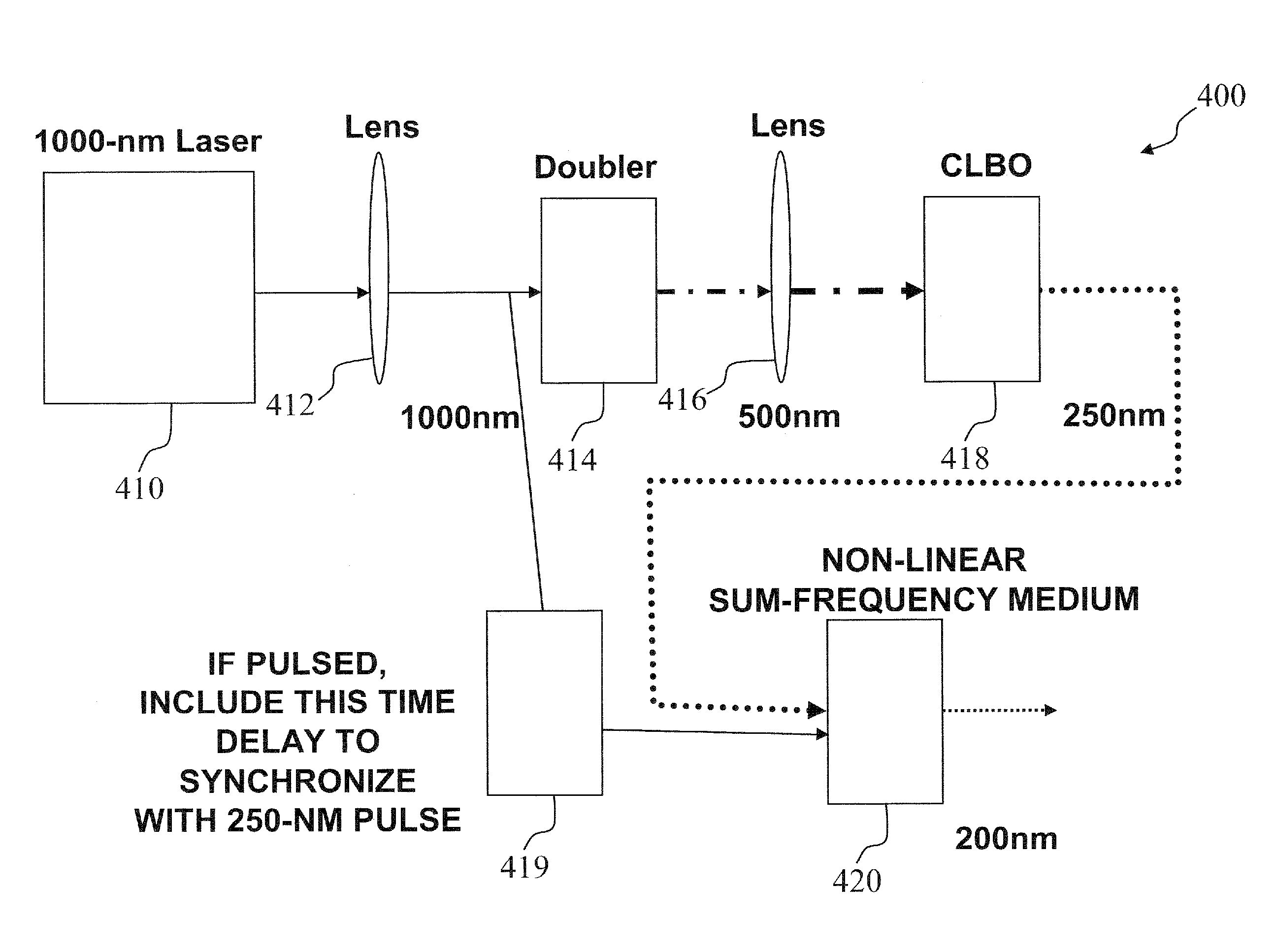
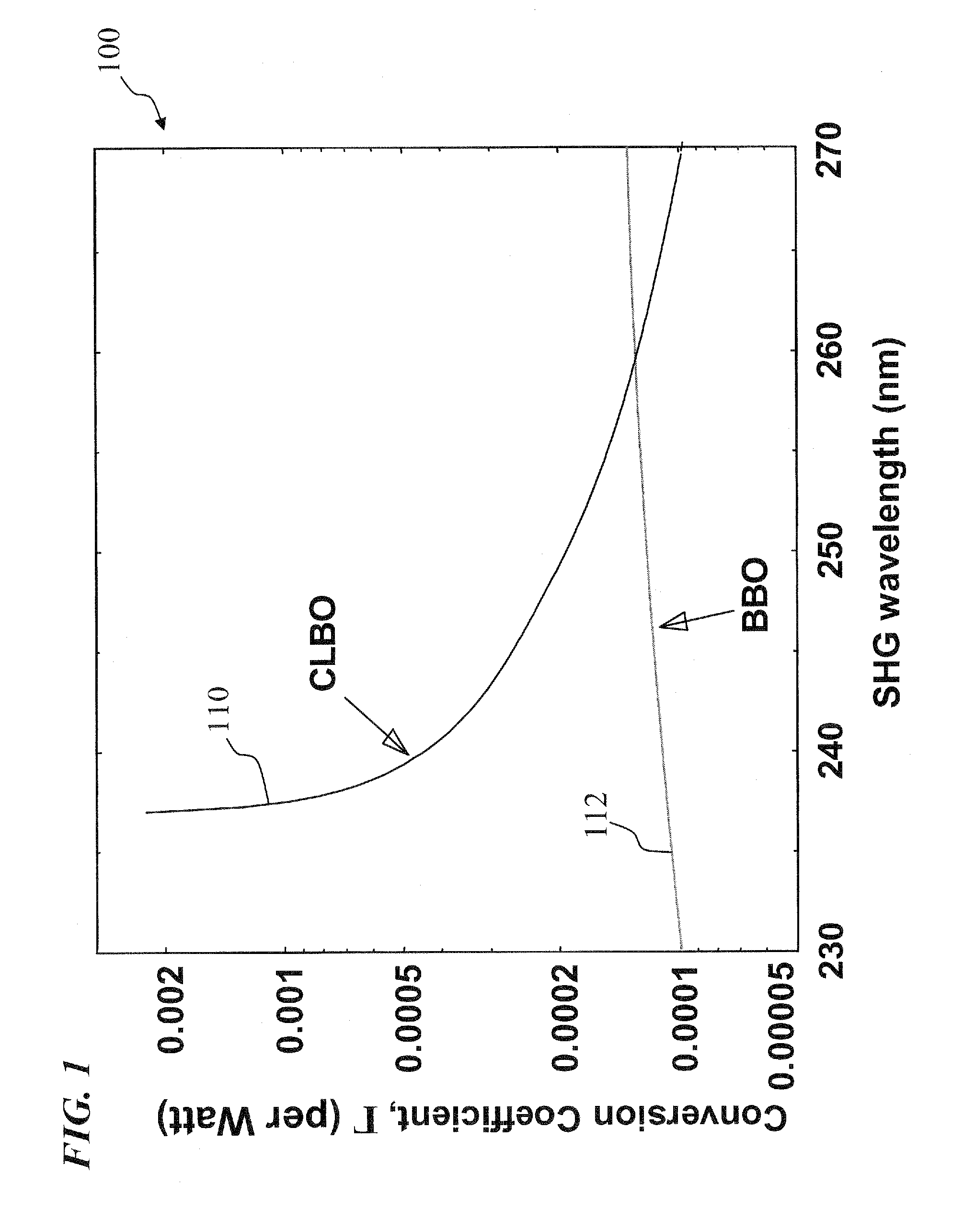
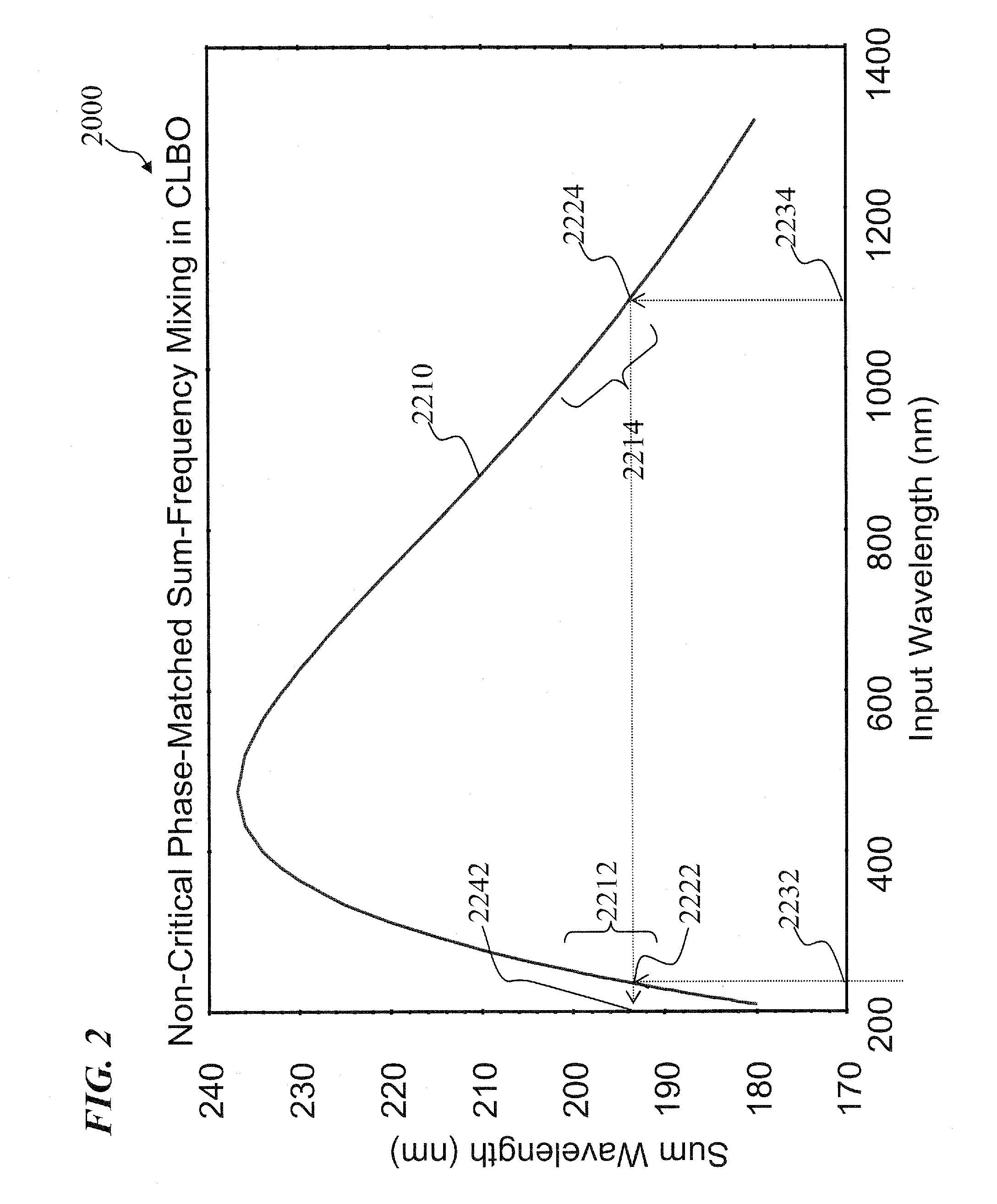
[0013] Of particular interest, in some embodiments, non-critically phase matched CLBO (cesium lithium borate) is used as the sum-frequency generation device, in order that high-efficiency conversion is obtained using a single source laser operating at about a 1000-nm wavelength. In some embodiments, the curve of highest-efficiency conversion for non-critically phase matched CLBO sum-frequency generation intersects input wavelengths at or almost exactly at 1000 nm input wavelength and 250 nm input wavelength (which is obtainable by frequency quadrupling the 1000 nm input wavelength), in order to obtain a 200-nm output wavelength. This provides inexpensive and highly efficient generation of 200 nm wavelength output light.

Problems solved by technology

Currently, there are no adequate laser sources for semiconductor inspection at these wavelengths.
These lasers are not suitable for scanning applications such as inspection.
Frequency-doubled ion lasers (FreDs) can provide continuous wave (cw) outputs at various wavelengths near and below 250 nm (for example, 257 nm and 244 nm), but these systems are very large, inefficient, costly, and relatively unreliable.
Laser systems employing photons from 244-nm FreD lasers combined with photons from 1064-nm solid-state lasers provide output photons at 198 nm (1 / 244+1 / 1064=1 / 198), but these systems are very complex, inefficient, costly, and relatively unreliable.
That approach also requires two separate lasers, which is undesirable for cost and complexity considerations.
Further, for pulsed operation, it is costly and difficult to adequately synchronize pulses from different pulsed laser sources.

Method used


Image

  • Ultraviolet laser system and method having wavelength in the 200-nm range
  • Ultraviolet laser system and method having wavelength in the 200-nm range
  • Ultraviolet laser system and method having wavelength in the 200-nm range

Examples


Embodiment Construction

[0018] Although the following detailed description contains many specifics for the purpose of illustration, a person of ordinary skill in the art will appreciate that many variations and alterations to the following details are within the scope of the invention. Accordingly, the following preferred embodiments of the invention is set forth without any loss of generality to, and without imposing limitations upon the claimed invention.

[0019] In the following detailed description of the preferred embodiments, reference is made to the accompanying drawings that form a part hereof, and in which are shown by way of illustration specific embodiments in which the invention may be practiced. It is understood that other embodiments may be utilized and structural changes may be made without departing from the scope of the present invention.

[0020] The leading digit(s) of reference numbers appearing in the Figures generally corresponds to the Figure number in which that component is first intr...


PUM


Abstract

An apparatus and method applicable for generating ultraviolet laser light having a wavelength in the 200-nm range and / or 250-nm range; in some embodiments, using a single fiber laser pump source (in some embodiments, a pulsed source). In some embodiments, the invention provides methods of generating 250-nm or 200-nm photons using a mode-locked 1000-nm fiber laser and efficient 4th / 5th harmonic frequency up-conversion. In other embodiments, the invention uses continuous wave (cw) single-frequency fiber lasers and external resonant frequency conversion. In still other embodiments, the invention uses cw single-frequency optically-pumped semiconductor lasers (OPSLs) and electrically driven vertical-cavity surface-emitting lasers (VCSELs) and externally resonant frequency conversion. All of these produce both of the ultraviolet wavelengths of interest.

Description

CROSS-REFERENCE TO RELATED APPLICATIONS [0001] This invention claims benefit of U.S. Provisional Patent Application 60 / 735,615 filed Nov. 9, 2005, which is hereby incorporated by reference in its entirety.FIELD OF THE INVENTION [0002] The invention relates generally to lasers and nonlinear optical frequency conversion and more particularly to methods and apparatus applicable for generating ultraviolet laser light having a wavelength in the 200-nm range and / or 250-nm range that use, in some embodiments, a single pulsed or cw (continuous wave) fiber-laser pump source, and non-critically phase matched CLBO (cesium lithium borate). BACKGROUND OF THE INVENTION [0003] A number of commercial applications require compact, efficient, and reliable laser systems in the ultraviolet wavelength range near and below 250 nm and also near and below 200 nm. [0004] One of these applications is inspection for the semiconductor manufacturing industry. This includes inspection of wafers during processing...

Claims


Application Information

Patent Timeline
IPC IPC(8): H01S3/10
CPCG02F2001/3507G02F1/3534G02F1/3507
Inventor GERSTENBERGER, DAVID C.BOWERS, MARK S.
Owner LOCKHEED MARTIN CORP
Learn More