Fluid Dynamic Bearing Mechanism for a Motor

a technology of dynamic bearing and motor, which is applied in the direction of sliding contact bearing, record information storage, instruments, etc., can solve the problems of small and thin fluid bearings, and achieve the effects of easy checking of the amount of lubricant, low cost, and high bearing rigidity and rotating accuracy

Inactive Publication Date: 2007-09-13
MINEBEA CO LTD
View PDF6 Cites 32 Cited by
  • Summary
  • Abstract
  • Description
  • Claims
  • Application Information

AI Technical Summary

Benefits of technology

[0014] The object of the present invention is to solve the above mentioned problems and provide a fluid dynamic bearing mechanism for a motor that can be built smaller and thinner, achieve a high bearing rigidity and rotating accuracy built into a thinner motor, protect the rotor member from external vibrations and shocks, and allow maintenance personnel to easily check the amount of the lubricant. Such motor being suitable for use in a hard disk drive.

Problems solved by technology

Moreover, although the thrust plate is omitted, the ring-shaped member provided on the tip of the shaft still prevents the fluid bearing from being made smaller and thinner.

Method used


Image

  • Fluid Dynamic Bearing Mechanism for a Motor
  • Fluid Dynamic Bearing Mechanism for a Motor
  • Fluid Dynamic Bearing Mechanism for a Motor

Examples


embodiment 1

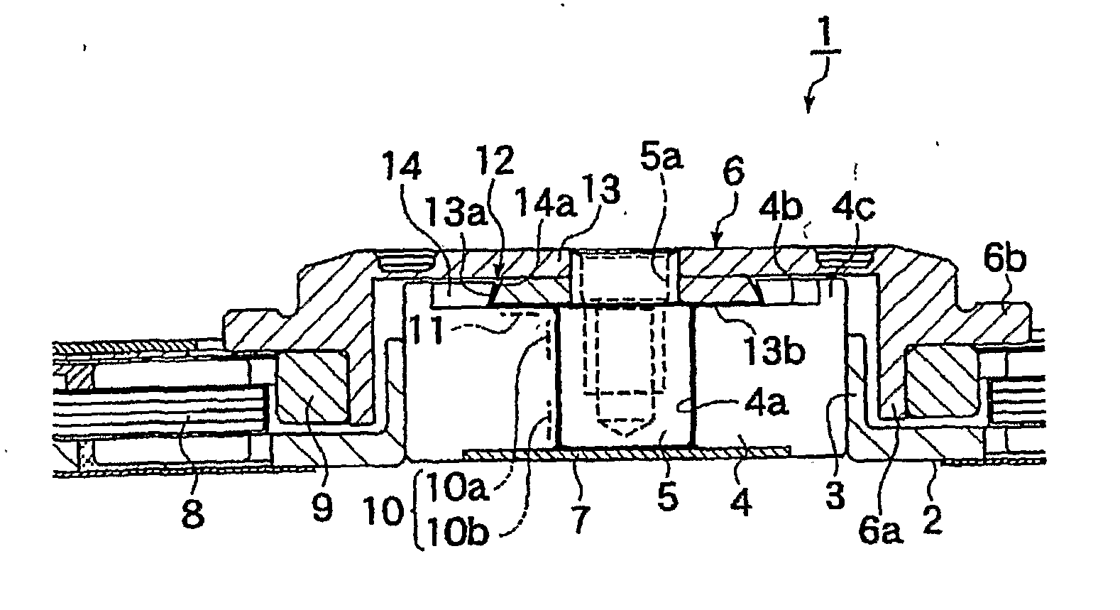
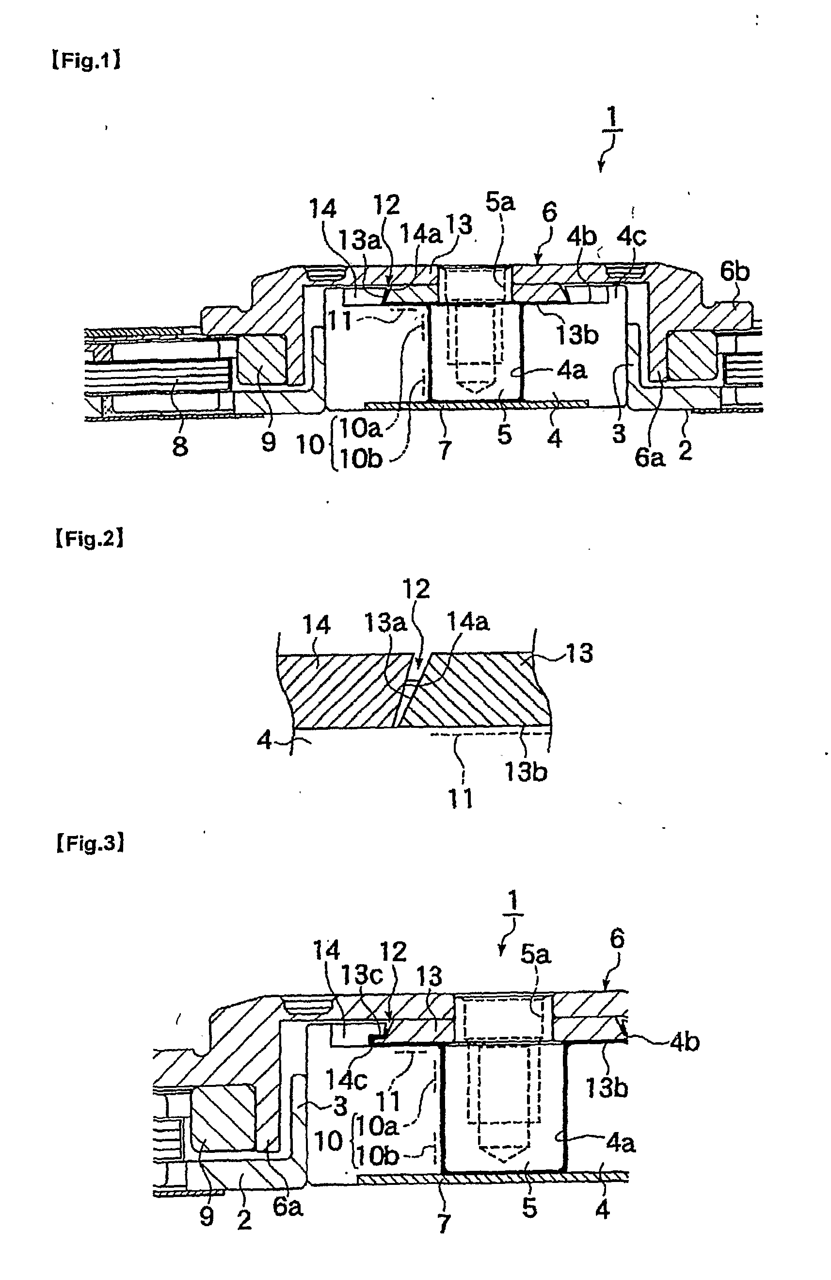
[0040]FIG. 1 is a vertical cross section of a motor 1 of Embodiment 1 and FIG. 2 is an enlarged view of a portion of FIG. 1. In Embodiment 1, the motor 1 is a spindle motor used to drive a hard disk drive. A cylindrical bearing holding member 3 provided vertically in the center of a base member 2 has mounted in it a cylindrical sleeve that forms a bearing member 4 of a fluid dynamic bearing mechanism. A bearing hole 4a formed in the center of the bearing member (sleeve) 4 rotatably supports a shaft member (shaft) 5 that functions as the rotating shaft.

[0041] An upper-direction reduced diameter end of shaft member 5 is fitted with a rotor member (rotor hub) 6 that rotates carrying a disk (not shown). The disk is mounted on the surface of a flange part 6b of rotor member 6 and is affixed on rotor member 6 by means of a clamp member (not shown). A screw hole 5a is formed on an end of shaft member 5 for fastening the clamp member and the rotor member 6 onto the shaft member 5 by a scre...

embodiment 2

[0053] The second embodiment (Embodiment 2) of the present invention will be described below.

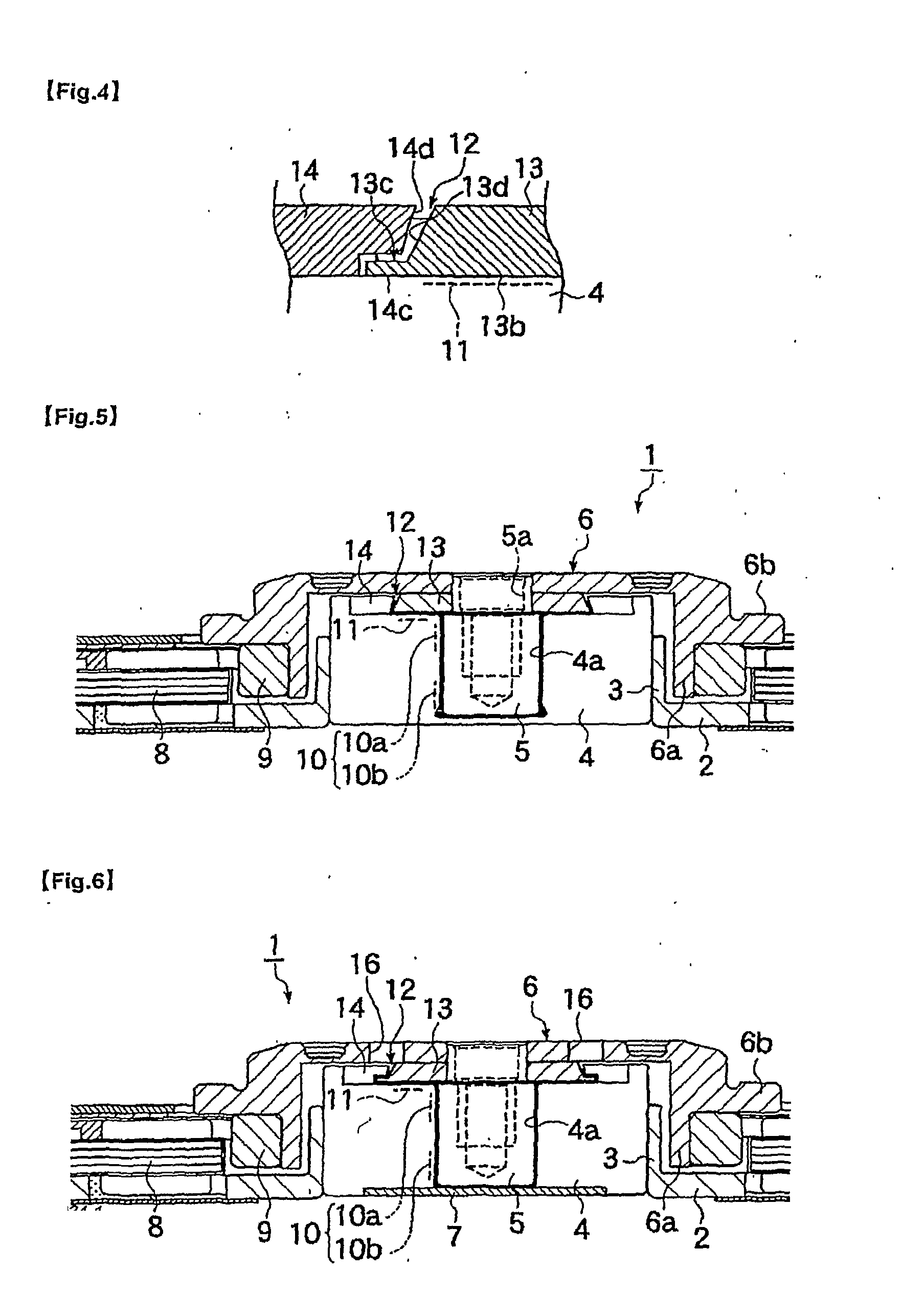
[0054]FIG. 3 is a vertical cross section of a motor 1 of Embodiment 2 and FIG. 4 is an enlarged view of a portion of FIG. 3. In Embodiment 2, the structure of the capillary seal part 12 of motor 1 is different from that in Embodiment 1. In Embodiment 2, a step 13c is provided in place of the taper 13a, and a step 14c is provided in place of the taper 14a.

[0055] These steps 13c and 14c are steps formed on the outer periphery surface of annular member on shaft member side 13 and the inner periphery surface of annular member on bearing member side 14 in the inward radial direction. Normally only one step is formed on these surfaces. The radial gap between a one half outer periphery surface portion 13d on one end in the axial direction of the step 13c (upper side in FIG. 3) and a one half inner periphery surface portion 14d on one end in the axial direction of the step 14c can be arranged eith...

embodiment 3

[0063] The third embodiment (Embodiment 3) of the present invention will be described below.

[0064]FIG. 5 is a vertical cross section of a motor 1 of Embodiment 3. In Embodiment 3, a bearing member 4 and a cover plate 7 that blocks the open end of a bearing hole 4a of the bearing member 4 are made of the same material as an integral part so that the cover plate 7 is not an independent part. Other than that, it is identical to Embodiment 1.

[0065] The construction of Embodiment 3 prevents the leakage of lubricant from the lubricant filling part to the outside almost completely except for the possibility of a slight leakage via the capillary seal part 12. Also, it simplifies the construction of the bearing member 4, reduces the number of components, and can reduce the assembly man-hours.

[0066] The integral structure of the cover plate 7 and bearing member 4 in Embodiment 3 can be applied to all other embodiments that use a cover plate.


PUM


Abstract

A fluid dynamic bearing mechanism for a motor (1) suitable for use in a hard disk drive and having a compact and thin shape, high bearing rigidity, and high rotating accuracy, and which securely keeps the rotor member (6) in place against shocks, and allows the inspection of lubricant supply amount easily. A fluid dynamic bearing mechanism having a capillary seal part (12) on one end of lubricant supply part formed by a minute gap including dynamic pressure grooves (10) formed on a shaft member (5) or a bearing member (4) is provided. An annular member (13) is fitted on the shaft member at the location corresponding to the capillary seal part, another annular member (14) is fitted on the bearing member at the location corresponding to the capillary seal part, a taper or step (13a, 14a) is formed on the outer peripheral surface of the annular member on the shaft member side and the inner peripheral surface of the annular member on the bearing member side. These inner and outer peripheral surfaces are arranged to be close to and facing with each other so that the rotor member is prevented from disengaging from the bearing member, and the capillary seal part can be formed at the same time. An axial dynamic pressure bearing unit (1) is formed between the annular member on the shaft member side and one end of the bearing member.

Description

BACKGROUND OF THE INVENTION [0001] 1. Field of the Invention [0002] The present invention relates to a fluid dynamic bearing mechanism for a motor, in particular, a fluid dynamic bearing mechanism suitable for motors such as small and thin spindle motors, that have an excellent bearing rigidity and rotation accuracy, can securely prevent the rotor member from dislodging under external vibrations and shocks and allows for verification of the amount of lubricant being supplied. [0003] 2. Description of Related Art [0004] Hard disk drives in recent years have become smaller and thinner, and begun running faster with the increasing memory capacity of hard disks. Consequently, the fluid dynamic bearing mechanism is required to be more compact and thinner as well as to have higher bearing rigidity, rotating accuracy, and reliability. Therefore, various kinds of improvements have been made in order to respond to those requirements. [0005] For example, Publication of Unexamined Japanese Pat...

Claims


Application Information

Patent Timeline
Patent Type & Authority Applications(United States)
IPC IPC(8): F16C32/06
CPCF16C33/107G11B19/2036F16C17/107F16C2370/12F16C33/745H02K5/1675
Inventor OBARA, RIKUROAKAHORI, TADASHI
Owner MINEBEA CO LTD
Why Eureka
Try Eureka