

Image forming method
Inactive Publication Date: 2007-09-13
CANON KK
View PDF6 Cites 7 Cited by
- Summary
- Abstract
- Description
- Claims
- Application Information
AI Technical Summary
Benefits of technology
[0013]A principal object of the present invention is to provide an image forming method capable of suppressing an occurrence of image flow in a short time by efficiently removing a discharge product while suppressing activation of the discharge product caused by actuation of a charger.
Problems solved by technology
As a result, a potential gradient of the electrostatic latent image cannot be maintained.
However, in such a moisture removal method in which moisture adsorbed at the surface of the image bearing member is removed by heating, a temperature is required to be changed, so that it takes a time.
Further, a large amount of electric power energy is consumed in the case of quick heating.
However, in the case where a degree of deterioration is large, e.g., in the case of a large amount of surface deposit, the surface deposit cannot be removed by a rubbing member such as the cleaning blade.
Method used
View moreImage
Smart ImageViewing Examples

Examples
first embodiment
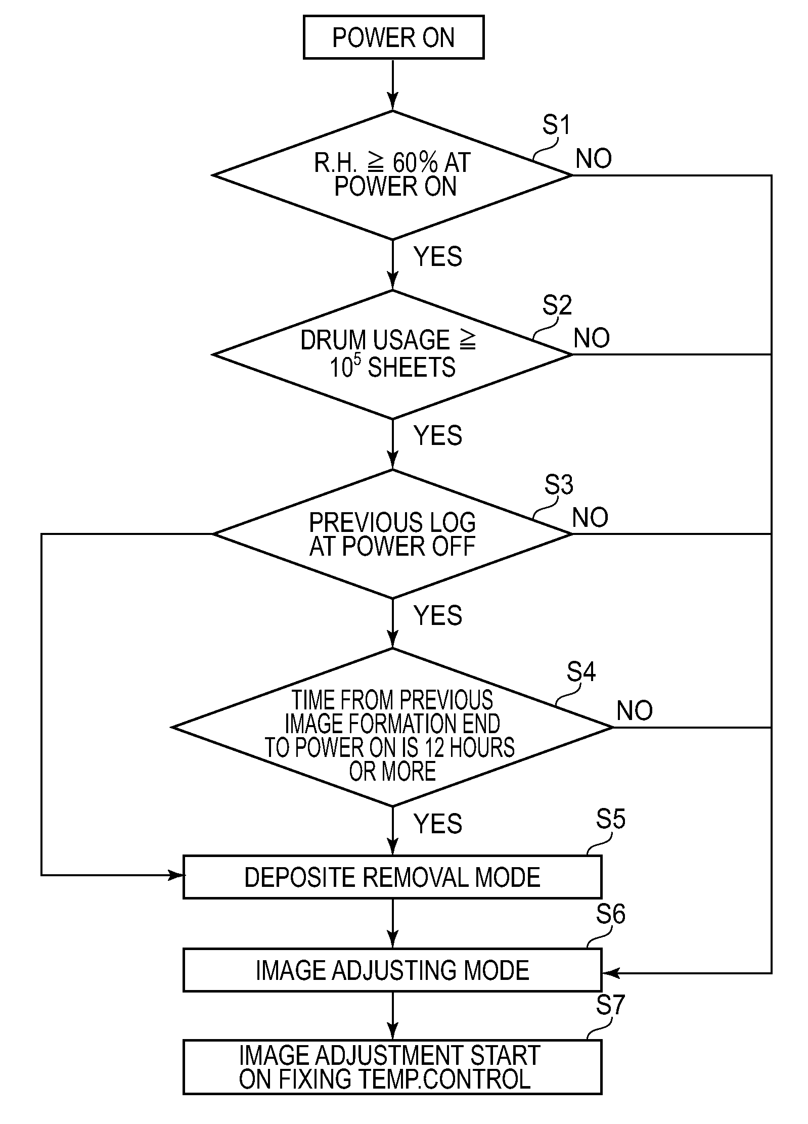
[0069]The image adjusting mode is such a mode that a charging condition or the like is adjusted by actuating a charger in advance of the image forming operation so as to obtain a predetermined charge potential.
[0070]As a result, a high-density line image having a width of about 200 μm could not be maintained and the resultant image was of such a poor level that a characteristic or the like was not recognizable. This is because moisture is adsorbed by photosensitive drum deposited on the photosensitive drum surface to lower a surface resistance of the photosensitive drum and thus an electrostatic latent image cannot be maintained to cause the image flow phenomenon.
Login to View More PUM
 Abstract
A band-like developer (toner) image is formed on an image bearing member by a developing member without performing a charging operation by a charger for electrically charging the image bearing member and then is removed by a cleaner. Thereafter, the charging operation is started after an area, in which the band-like developer image is removed by the cleaner, passes through an opposing portion between the image bearing member and the charger.
Description
FIELD OF THE INVENTION AND RELATED ART[0001]The present invention relates to an image forming method, particularly a constitution for preventing an occurrence of image flow.[0002]In a conventional image forming apparatus such as a printer, a copying machine, a facsimile apparatus, etc., image formation is performed by disposing a charging means, an exposure means, a developing means, a transfer means, and a cleaning means at positions each adapted to an associated step. During the image formation, first, an image bearing member is electrically charged uniformly in the dark by the charging means (in a charging step).[0003]When a charging (discharging) operation is effected by the charging means or the like, a discharge product such as nitrogen oxide or the like is generated and deposited on a surface of the image bearing member in some cases. The surface of the image bearing member has a surface resistance higher than that of water, so that electric charges on the image bearing membe...
Claims
Login to View More Application Information
Patent Timeline
 IPC IPC(8): G03G15/00G03G21/00
CPCG03G21/0005
InventorHISAKUNI, HISATAKA
OwnerCANON KK