

Segmented component seal
a technology of components and seals, applied in the direction of machines/engines, stators, liquid fuel engines, etc., can solve the problems of premature oxidation of components, cracks, and increase the fuel burn of engines
- Summary
- Abstract
- Description
- Claims
- Application Information
AI Technical Summary
Benefits of technology
Problems solved by technology
Method used
Image

Examples
Embodiment Construction
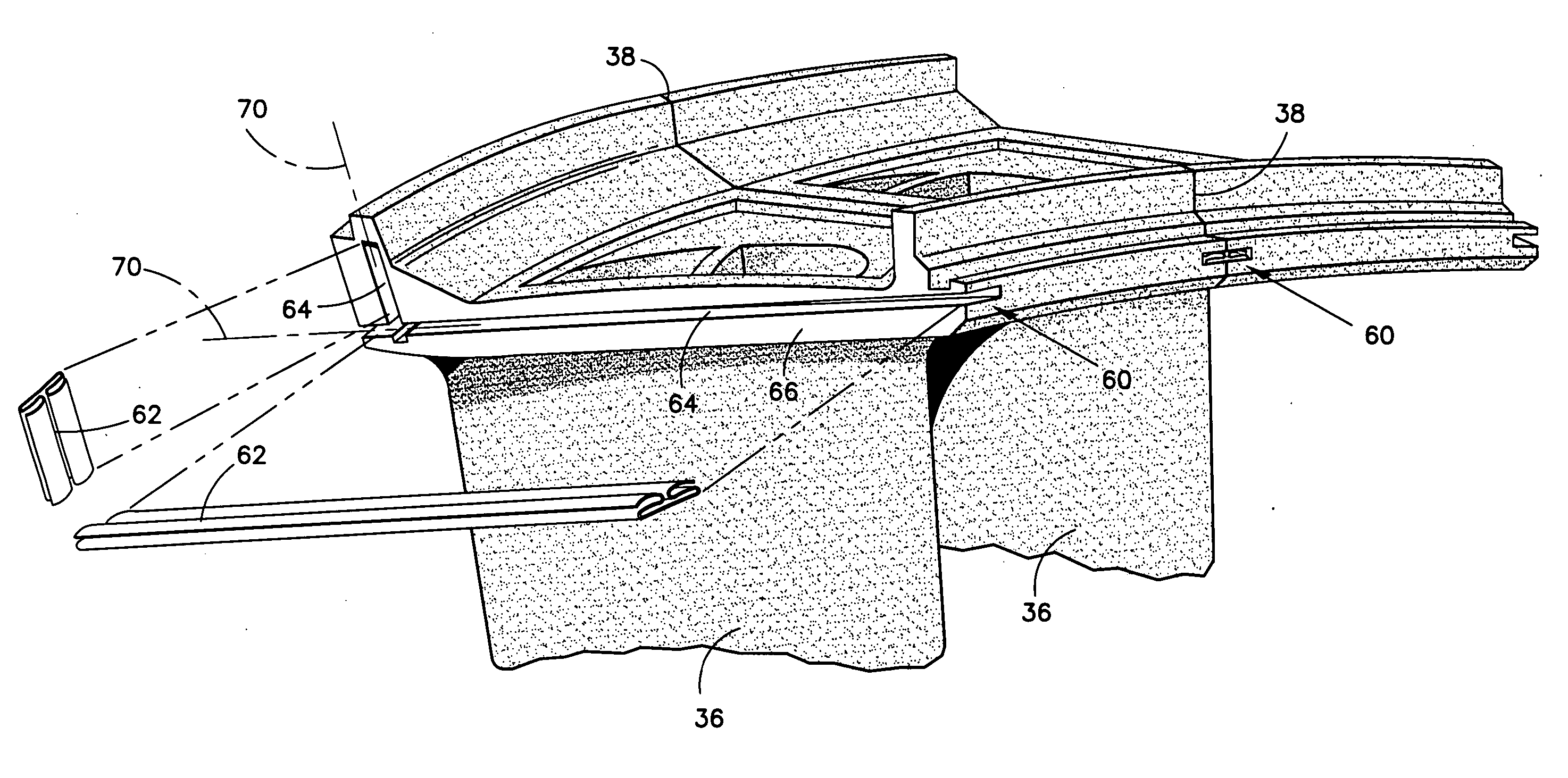
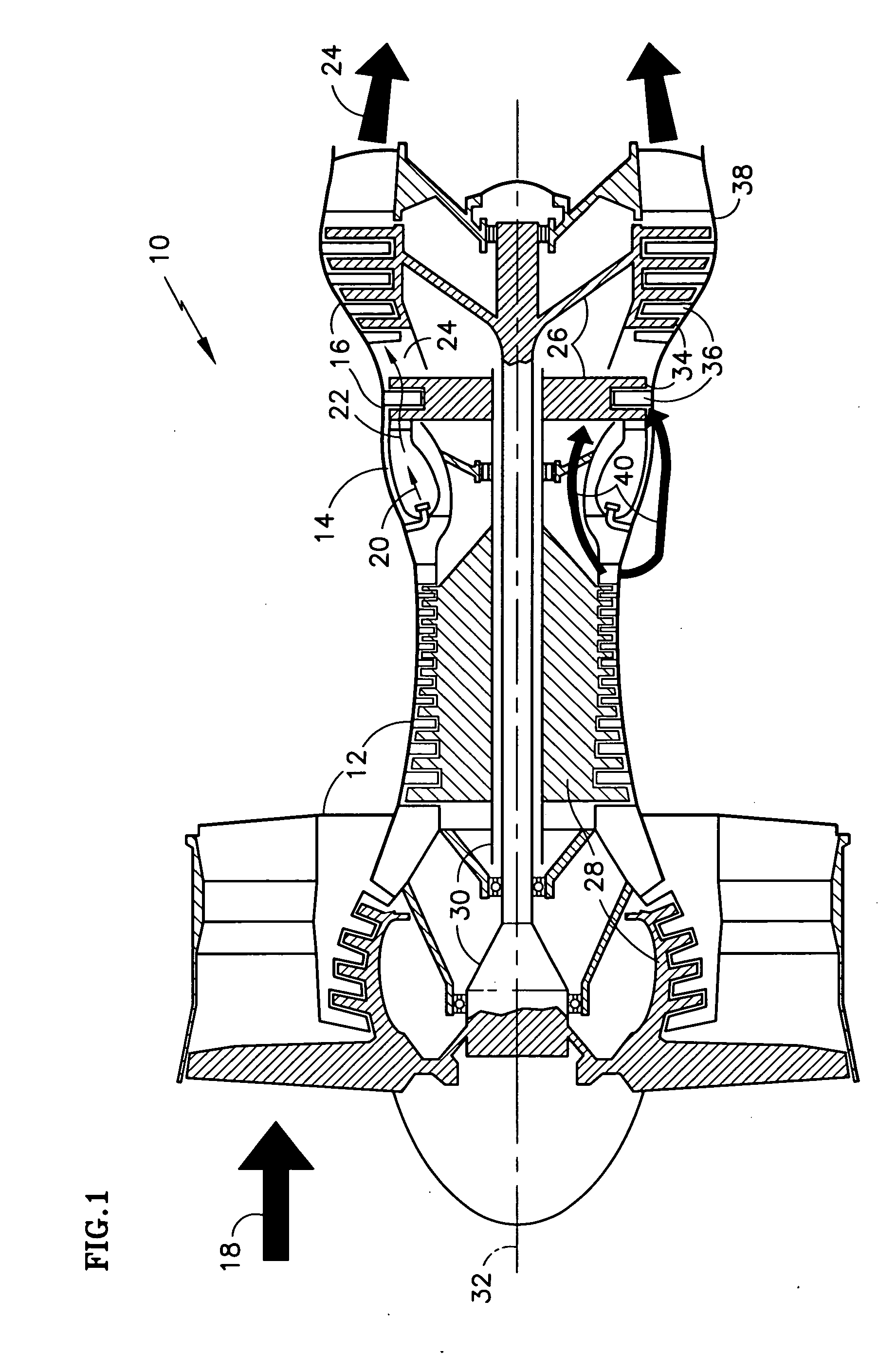
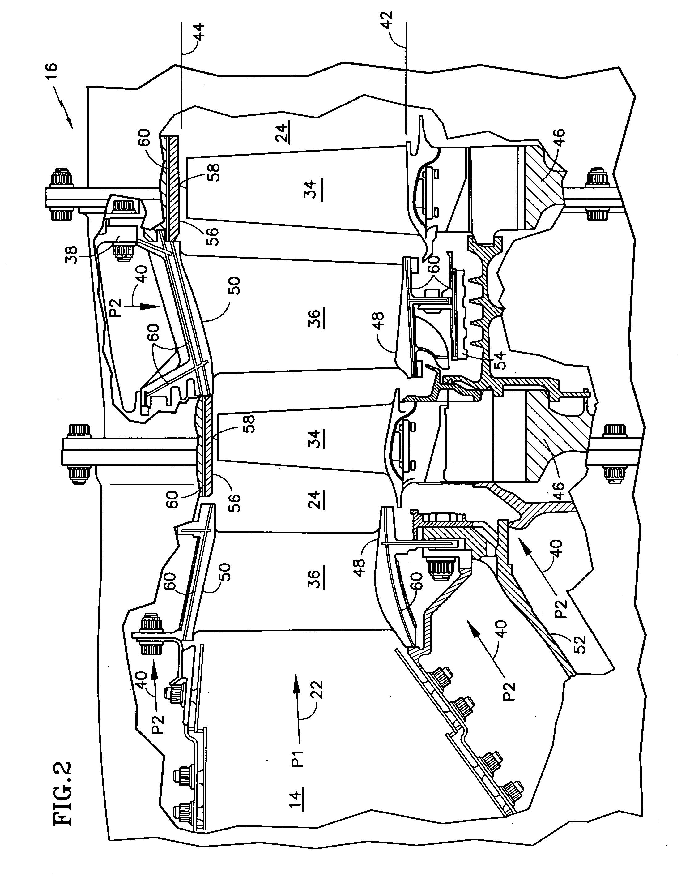
[0023] An exemplary turbine 16 of a gas turbine engine 10 is illustrated in FIG. 2. The high temperature combustion gases 22 discharge rearward from the combustor 14, at a pressure (P1), to an annular duct 24 defined by an inner periphery 42 and an outer periphery 44. Stationary vanes 36 guide the combustion gases 22 to rotating blades 34, extending radially outwardly from rotor disks 46. The vanes 36 span radially between inner 48 and outer 50 shrouds, which are suspended from an inner support 52 and / or outer casing 38 structures. Inner seals 54 restrict leakage of the combustion gases 22 from beneath the vanes 36 at the inner periphery 42. Outer seals 56 restrict leakage of the combustion gases 22 from above tips 58 of the blades 34 at the outer periphery 44.
[0024] Those skilled in the art will appreciate that each of the above-described turbine 16 components must be actively cooled, because the combustion gas 22 temperature typically exceeds the melting temperatures of the compo...
PUM
 Abstract
Description
Claims
Application Information