Variable displacement vane pump and method of controlling the same

a vane pump, variable-displacement technology, applied in the direction of machines/engines, positive-displacement liquid engines, liquid fuel engines, etc., can solve the problems and achieve the effect of increasing the size and weight of the solenoid valve and sufficient capability

Inactive Publication Date: 2007-09-13
HITACHI LTD
View PDF0 Cites 31 Cited by
  • Summary
  • Abstract
  • Description
  • Claims
  • Application Information

AI Technical Summary

Benefits of technology

[0003]The variable displacement vane pump disclosed in Japanese Patent Application Publication No. 2004-218430 is confronted at least with the following problems. First, the cam ring starts to move after a delay from the time when the solenoid valve receives a drive signal, because the control valve operates at an intermediate stage. Second, the solenoid valve needs to have a sufficient capability to move against a high level of fluid pressure, because the solenoid valve is subject in the direction of movement to the high discharge pressures introduced into the control valve. This tends to increase the size and weight of the solenoid valve.

Problems solved by technology

Second, the solenoid valve needs to have a sufficient capability to move against a high level of fluid pressure, because the solenoid valve is subject in the direction of movement to the high discharge pressures introduced into the control valve.
This tends to increase the size and weight of the solenoid valve.

Method used


Image

  • Variable displacement vane pump and method of controlling the same
  • Variable displacement vane pump and method of controlling the same
  • Variable displacement vane pump and method of controlling the same

Examples


first embodiment

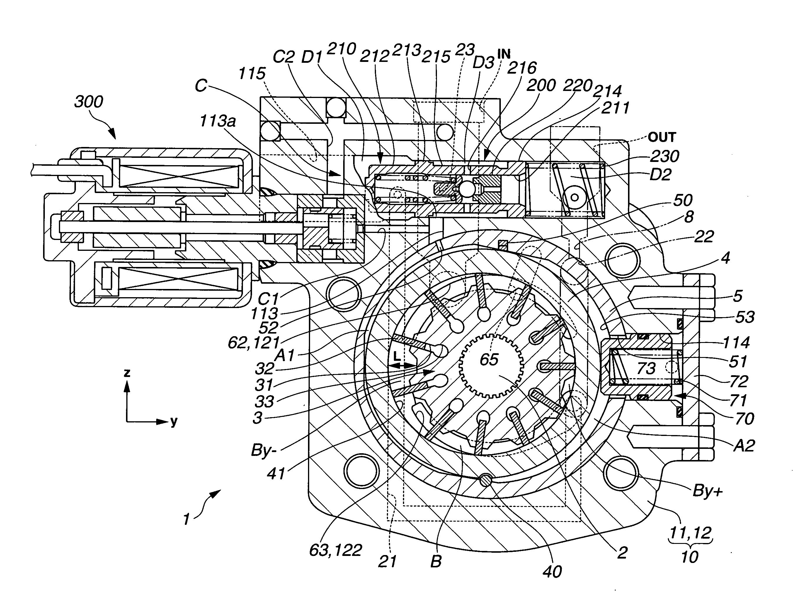
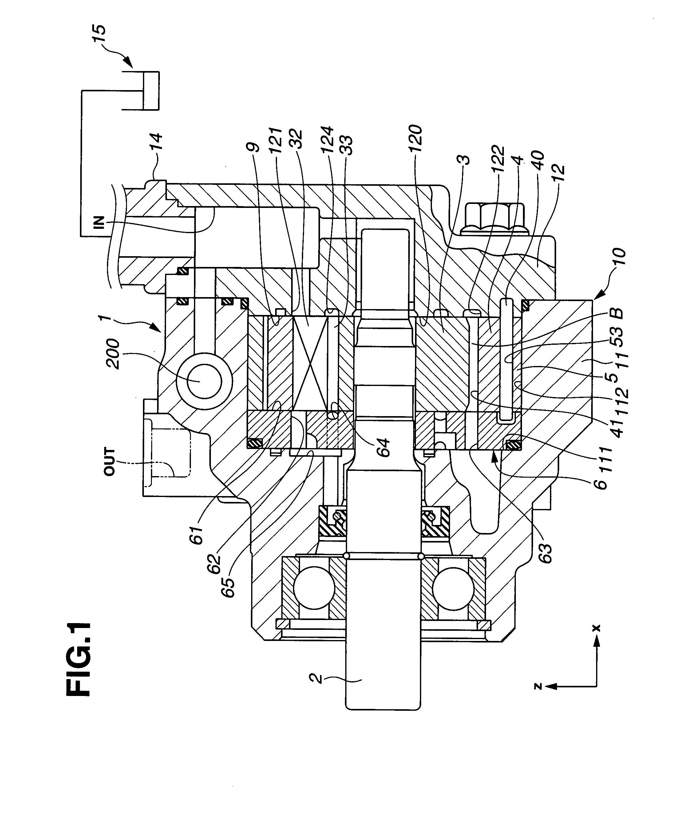
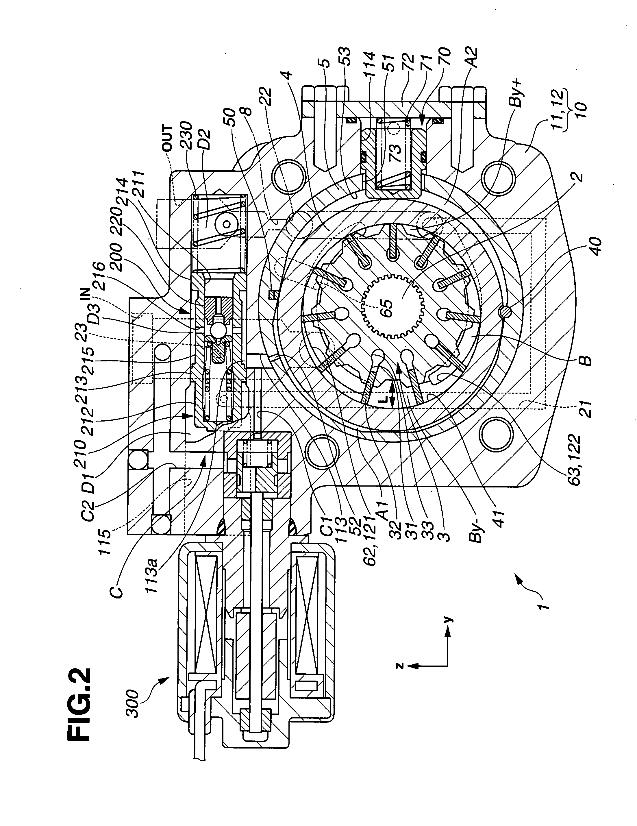
[0030]FIGS. 1, 2, 3 and 4 show a variable displacement vane pump in accordance with the present invention. A right-handed rectangular coordinate system (xyz) is provided in the drawings. In this variable displacement vane pump, a controlled fluid pressure is introduced into a first fluid pressure chamber, while a suction pressure is introduced into a second fluid pressure chamber, as described below in detail.

[0031]A variable displacement vane pump 1 generally includes a drive shaft 2, a rotor 3, a cam ring 4, an adapter ring 5, a pump body 10, a control valve 200, and an electromagnetic valve 300 in the form of a solenoid valve. Cam ring 4 is movably mounted within pump body 10, defining first and second fluid pressure chambers A1 and A2. Rotor 3 is mounted inside cam ring 4 at least for rotation about an axis in a direction, defining an annular chamber outside thereof. The axis of rotor 3 extends in the x-direction, while the direction of rotation of rotor 3 is counterclockwise as...

third embodiment

[0086]In the third embodiment, solenoid valve 300 is disposed on the positive y side and on the positive z side of adapter ring 5 in first housing 11 as shown in FIG. 9. Solenoid valve 300 is hydraulically connected to third fluid pressure chamber A3 through the fluid communication passage C3, and to suction passage IN through the fluid communication passage C4. Thus, third fluid pressure chamber A3 is connected to suction passage IN through the solenoid valve 300. Solenoid valve 300 selectively connects and disconnects the third fluid pressure chamber A3 to and from suction passage IN. While the internal pressure of third fluid pressure chamber A3 is equal to mixed pressure Pm (higher than suction pressure Pin), the opening operation of solenoid valve 300 allows the working fluid within third fluid pressure chamber A3 to flow out to suction passage IN, reducing the internal pressure of third fluid pressure chamber A3, P3.

[0087]FIG. 10 shows a variable displacement vane pump in acco...

fourth embodiment

[0090]FIG. 12 shows a variable displacement vane pump in accordance with a modification of the In this modification, solenoid valve 300 is hydraulically connected to discharge passage OUT through a fluid communication passage C4a. Solenoid valve 300 selectively connects and disconnects the third fluid pressure chamber A3 to and from discharge passage OUT. Control valve 200 constantly introduces the downstream discharge pressure Pfb into third fluid pressure chamber A3. While solenoid valve 300 is in an open state, the internal pressure of third fluid pressure chamber A3 is increased because downstream discharge pressure Pfb is lower than discharge pressure Pout.

[0091]FIGS. 13, 14 and 15 show a variable displacement vane pump in accordance with a fifth embodiment of the present invention. The fifth embodiment differs from the first embodiment in that the solenoid valve 300 is disposed close to suction passage IN, and solenoid valve 300 is hydraulically connected to first fluid press...


PUM


Abstract

A variable displacement vane pump includes: a cam ring defining first and second fluid pressure chambers on both sides thereof; and a rotor mounted inside the cam ring, the rotor defining an annular chamber outside thereof. Arranged outside of the rotor, vanes divide the annular chamber into a plurality of pump chambers. A suction port is defined in a section of the annular chamber in which each of the pump chambers expands with the rotation of the rotor, while a discharge port is defined in a section of the annular chamber in which each of the pump chambers contracts with the rotation of the rotor. A first fluid passage is connected to one of the first and second fluid pressure chambers. A second fluid passage is connected to one of the suction port and the discharge port. An electromagnetic valve controls fluid communication between the first and second fluid passages.

Description

BACKGROUND OF THE INVENTION[0001]The present invention relates generally to variable displacement pumps, and more particularly to variable displacement vane pumps useful for power steering systems.[0002]Japanese Patent Application Publication No. 2004-218430 shows a variable displacement vane pump including a rotor and a cam ring surrounding the rotor in which working fluid flows circumferentially between the rotor and the cam ring. The cam ring is mounted for swinging motion. As the cam ring is displaced to alter the shape of the space defined between the rotor and the cam ring, the discharge quantity of this pump varies. The swinging motion of the cam ring is controlled by a control valve through two opposed fluid pressure chambers. The control valve includes a pilot chamber for receiving a fluid pressure from a downstream portion of a discharge passage with respect to an orifice. Provided in a fluid passage extending between the second pilot chamber and a fluid tank, a solenoid v...

Claims


Application Information

Patent Timeline
Patent Type & Authority Applications(United States)
IPC IPC(8): F01C20/18
CPCF04C2/3442F04C14/226F04C2270/21F04C15/0034F04C2270/18F04C14/26
Inventor YAMAMURO, SHIGEAKIKONISHI, HIDEOSEMBA, FUSAO
Owner HITACHI LTD
Why Eureka
Try Eureka