Physiological event detection systems and methods

a detection system and physiological technology, applied in the field of physiological event detection systems and methods, can solve the problems of determining the time of an event, identifying when measurements indicate a condition, and identifying a condition even more difficul

Inactive Publication Date: 2007-09-13
CARDIAC PACEMAKERS INC
View PDF6 Cites 103 Cited by
  • Summary
  • Abstract
  • Description
  • Claims
  • Application Information

AI Technical Summary

Problems solved by technology

Measuring each of these parameters and correctly identifying when measurements indicate a condition is difficult.
Identifying a condition becomes even more difficult when some measurements indicate the onset or existence of a condition or disease while others do not.
It is difficult, however, to determine when an event is beginning when only some measurements for these parameters indicate the onset of a condition.
Configuring the pulse generator can therefore become a tedious, time-consuming exercise that may involve guesswork on the part of the clinician.
In some circumstances, such as defibrillation shock therapy, the user of the implantable medical device receives painful and unnecessary treatment in response to such a false positive.
It may therefore be difficult for a clinician to observe differences in the joint metric J and the confidences C1 or C2 over time.
In practice, multidimensional distributions are difficult to estimate from limited data, and are computationally cumbersome.
While this may be desirable, in certain circumstances, in other circumstances it may be undesirable.
In such an example, even if the adaptive threshold has not been triggered because of the gradual nature of the change in the physiological parameter, a secondary static threshold may still result in the declaration that an abnormal event or condition has occurred.
In certain examples, stored measurements deemed corrupt, invalid (e.g., because confounded by one or more other physiological parameters, or because they relate to a measured event or condition, or because they are associated with a malfunctioning sensor, etc.), etc. are stored, but are not used to compute the probability distribution function.

Method used


Image

  • Physiological event detection systems and methods
  • Physiological event detection systems and methods
  • Physiological event detection systems and methods

Examples


Embodiment Construction

[0021] The following detailed description includes references to the accompanying drawings, which form a part of the detailed description. The drawings show, by way of illustration, specific embodiments in which the invention may be practiced. These embodiments, which are also referred to herein as “examples,” are described in enough detail to enable those skilled in the art to practice the invention. The embodiments may be combined, other embodiments may be utilized, or structural, logical and electrical changes may be made without departing from the scope of the present invention. The following detailed description is, therefore, not to be taken in a limiting sense, and the scope of the present invention is defined by the appended claims and their equivalents.

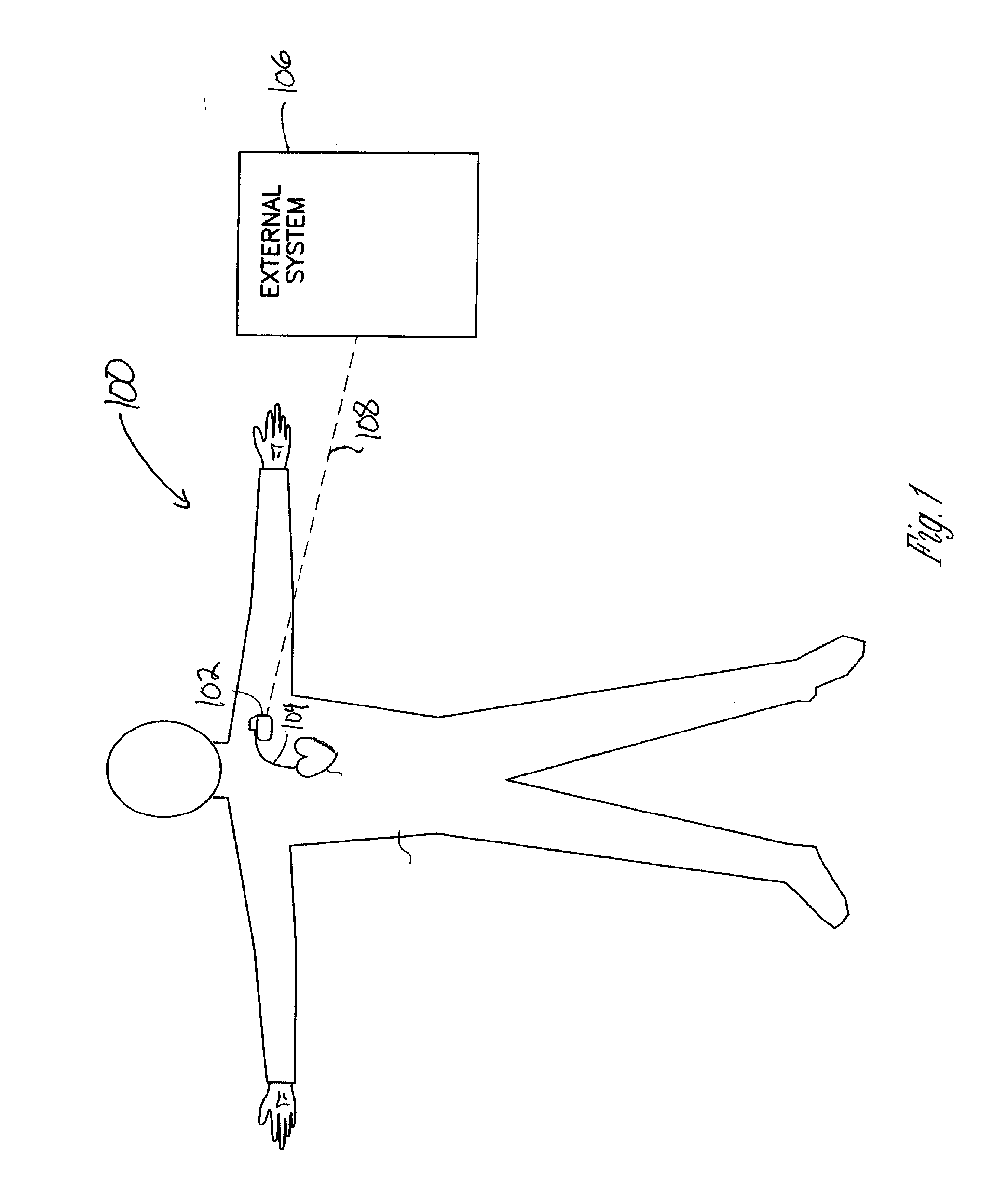
[0022]FIG. 1 is a schematic diagram showing one example of portions of a cardiac management system 100 including an implantable medical device 102, a lead system 104, an external system 106, and a wireless telemetry link 108...


PUM


Abstract

Systems and methods using constant false alarm rate techniques for event detection. One example of an event detection method includes collecting a first distribution of measurements for a first physiological parameter. In another example, the first distribution of measurements includes only non-event measurements. One or more values are determined corresponding to at least a first tail area of the first distribution from at least one measurement of the first physiological parameter toward an end point of the distribution. A threshold is established based on a specified false alarm rate. The one or more values are compared to the threshold. The method includes determining if the measurement is representative of a detected event using the comparison.

Description

TECHNICAL FIELD [0001] The technical field includes event detection with biomedical devices and in particular event detection using constant false alarm rate techniques. BACKGROUND [0002] The body includes a plurality of organs and systems that perform functions necessary for maintaining the health of a person. The circulatory system is one example of a system that includes the heart organ as its centerpiece. Other body systems include the respiratory system, digestive system, endocrine system, nervous system and the like. The organs of these systems provide a variety of physiological parameters useful for observing the normal and abnormal behaviors of the body. Observation of these parameters and recognition of potential normal and abnormal events through observation allows effective diagnosis or treatment of diseases, conditions and the like. The complexity of the various systems of the body provide multiple parameters that, when observed, provide insight regarding the onset of a ...

Claims


Application Information

Patent Timeline
Patent Type & Authority Applications(United States)
IPC IPC(8): A61B5/00G08B1/08
CPCA61B5/00A61B5/053A61N1/36514A61N1/3627A61B7/023A61B5/746G16H40/63G16H40/40
Inventor SIEJKO, KRZYSZTOF Z.HATLESTAD, JOHN D.
Owner CARDIAC PACEMAKERS INC
Why Eureka
Try Eureka