Tire Deformation Calculating Method And Tire Deformation Calculating Apparatus

a tire deformation and calculating method technology, applied in the direction of using mechanical means, electrical/magnetic measurement arrangements, amplifier modifications to reduce noise influence, etc., can solve the problem of difficult to obtain the deformation shape of the tread portion or the contact length in a short period of time, and achieve greater weighting coefficient, greater weighting coefficient, and greater accuracy

Inactive Publication Date: 2007-09-13
THE YOKOHAMA RUBBER CO LTD
View PDF11 Cites 25 Cited by
  • Summary
  • Abstract
  • Description
  • Claims
  • Application Information

AI Technical Summary

Benefits of technology

[0024] The present invention enables calculation of a deformation of a tire that is rotating on a road surface by using measurement data of acceleration obtained at a predetermined portion, for example, at a tread portion. Particularly, if the predetermined portion of the tire is the tread portion, a region on a tire circumference at the tire tread portion is divided into a first region including a contact region in contact with the road surface, and a second region including other than the first region, and by approximating the measurement data of acceleration in the second region, a first approximation curve defined in the first and second regions is calculated. Accordingly, background components including acceleration components of the centrifugal force (centripetal force) due to rotation of the tire and acceleration components of the gravitational force can be effectively obtained. In particular, since the first approximation curve is calculated through approximation of the time series data of acceleration in the first and second regions by providing a plurality of nodes in the second region and since the first approximation curve is calculated by applying a greater weighting coefficient to the time series of acceleration in the second region than a weighting coefficient applied to the time series data in the first region, the background components can be obtained with higher accuracy.
[0025] In addition, a region on a tire circumference at the tire tread portion is divided into a third region including a contact region in contact with the road surface, and a fourth region including other than the third region and by approximating displacement data in the fourth region, a second approximation curve defined in the third and fourth regions is calculated. The background components can thereby be obtained in such a manner that the deformation of the tire cyclically changes with the rotation of the tire. In particular, since the second approximation curve is calculated through approximation of the displacement data in the third and fourth regions by providing a plurality of nodes in the fourth region, and since the second approximation curve is calculated by applying a greater weighting coefficient to the time series data of acceleration in the fourth region than a weighting coefficient applied to the time series data of acceleration in the third region, the background components can be obtained with higher accuracy.

Problems solved by technology

In such acquiring methods, however, because of the time required for preparing finite element models as well as required for simulation computing, it has been difficult to obtain the deformation shape of the tread portion or the contact length in a short period of time.
However, any one of the Patent Documents 1 to 3 does not allow the deformation shape and the contact length of a rotating tire to be calculated from the measurement data of acceleration, though it is possible to estimate the status of the road surface using the measurement data.

Method used


Image

  • Tire Deformation Calculating Method And Tire Deformation Calculating Apparatus
  • Tire Deformation Calculating Method And Tire Deformation Calculating Apparatus
  • Tire Deformation Calculating Method And Tire Deformation Calculating Apparatus

Examples


Embodiment Construction

[0046] Hereinafter, the tire deformation calculating method and the tire deformation calculating apparatus according to the present invention will be described in detail with reference to the preferred embodiments shown in the attached drawings.

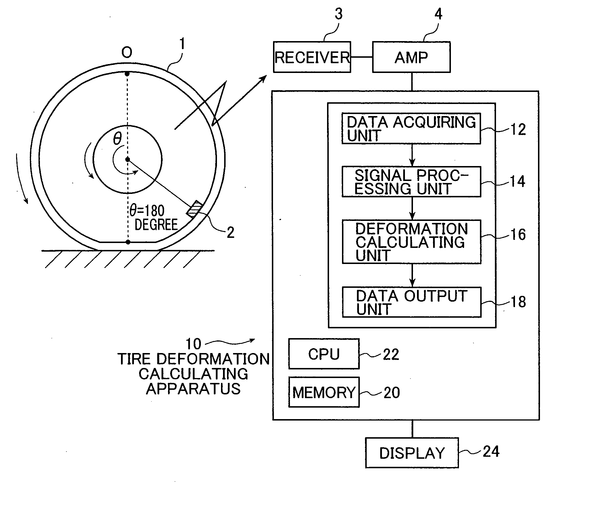
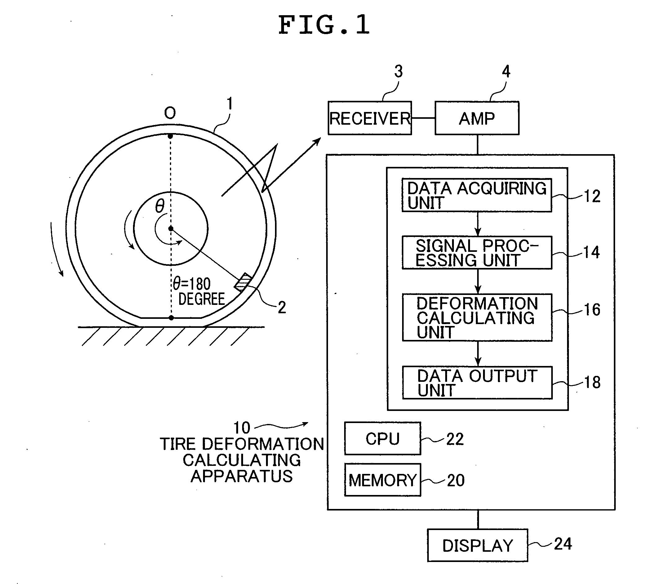
[0047]FIG. 1 is a block diagram showing a structure of an embodiment of the tire deformation calculating apparatus according to the present invention that implements the tire deformation calculating method according to the present invention.

[0048] The embodiment described below uses the measurement data of acceleration which is measured on an inner circumference surface at a tread portion of a tire. However, in the practice of the present invention, the measurement data of acceleration to be used is not limited to that obtained at the tread portion. The measurement data of acceleration may be those obtained inside the tread portion, at the belt portion, at the side portion or the like.

[0049] A tire deformation calculating apparatus 10 show...


PUM


Abstract

A deformation of a rotating tire on a road surface is calculated the following. At first, time series data of acceleration extracted from measurement data of acceleration corresponding to one round of tire rotation is subjected to a time integration of second order to obtain displacement data so as to calculate the deformation at the tread portion. The time series data of acceleration and the displacement data in the non-contact region excluding a road surface contact region on the tire circumference at the tread portion are respectively approximated to calculate a first and a second approximation curves. The two approximation curves are subtracted respectively from the time series data of acceleration and the calculated displacement data, thereby extracting time series data of acceleration due to tire deformation and obtaining the deformation at the tread portion.

Description

TECHNICAL FIELD [0001] The present invention relates to a tire deformation calculating method and a tire deformation calculating apparatus that calculate a deformation on a tire circumference at a predetermined portion of a tire which is rotating on a road surface by using measurement data of acceleration acquired by an acceleration sensor or other suitable devices provided on the predetermined portion of the tire. In particular, the present invention relates to a tire deformation calculating method and a tire deformation calculating apparatus that calculate a deformation on a tire circumference at a tread portion of a tire which is rotating on a road surface by using measurement data of acceleration acquired by an acceleration sensor or other suitable devices provided on the tread portion of the tire. BACKGROUND ART [0002] Conventionally, finite element models have been used to simulate a rotating tire, in order to acquire a contact length or distribution of deformation (deformatio...

Claims


Application Information

Patent Timeline
Patent Type & Authority Applications(United States)
IPC IPC(8): G06F17/40
CPCG01B21/32
Inventor KITAZAKI, TSUYOSHIMIYASHITA, NAOSHIKOGUCHI, NORITAKA
Owner THE YOKOHAMA RUBBER CO LTD
Why Eureka
Try Eureka