
Power cycle circuit

Active Publication Date: 2007-09-13
WSOU INVESTMENTS LLC
View PDF7 Cites 17 Cited by
  • Summary
  • Abstract
  • Description
  • Claims
  • Application Information

AI Technical Summary

Benefits of technology

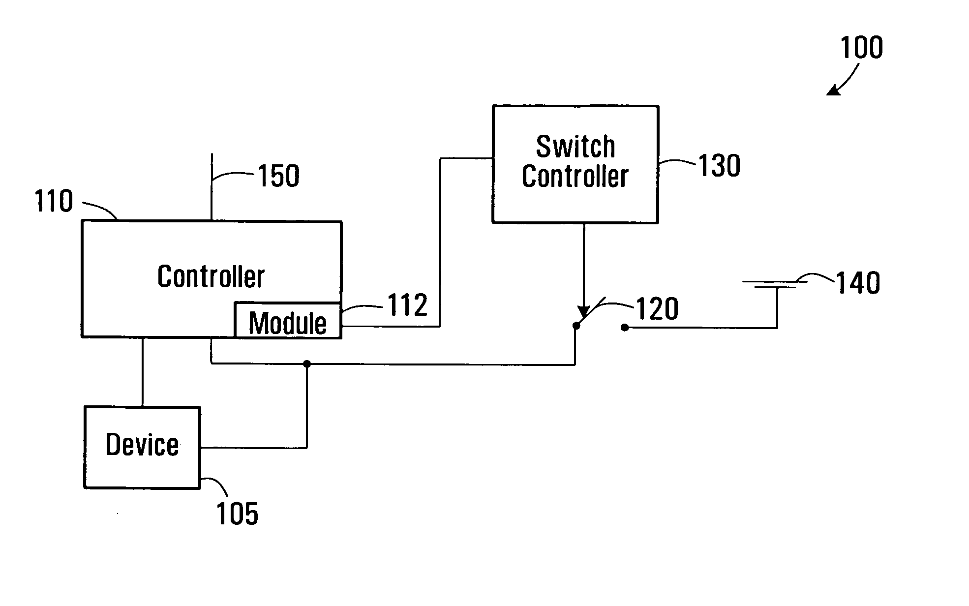
[0006] In some embodiments, the switch is adapted to switchably couple electrical power to the controller to enable the controller to operate, the module is arranged for controlling the switch to decouple electrical power from the device and the controller, and the switch controller is adapted for controlling the switch to restore electrical power to the device and to the controller a predetermined time after the switch decouples the electrical power from the device and the controller. In this arrangement, the module controls switching off of power to both the device and to itself. The switch controller controls the switch to restore electrical power both to the controller and to the device. This arrangement provides a simple and inexpensive means of implementing a power cycle capability. For example, where the apparatus includes a switchable device, such as a power converter, for providing power both to the controller and the device, the arrangement enables a power cycle to be performed simply by controlling the switchable device.
[0008] In some embodiments, the controller may include an interface for receiving a signal from a remote location to cause the controller to shut down power to the device, and optionally to itself. This arrangement enables a line card processor to be controlled from a remote location to perform a power cycle on the line card, thereby obviating the need for personnel to physically visit the location of the network element. For example, the power cycle control signal may be sent remotely from a network management system (NMS). Furthermore, since the reset is controlled by the line card's local processor and is performed on itself, line cards can be controlled individually to reset themselves without effecting other line cards.
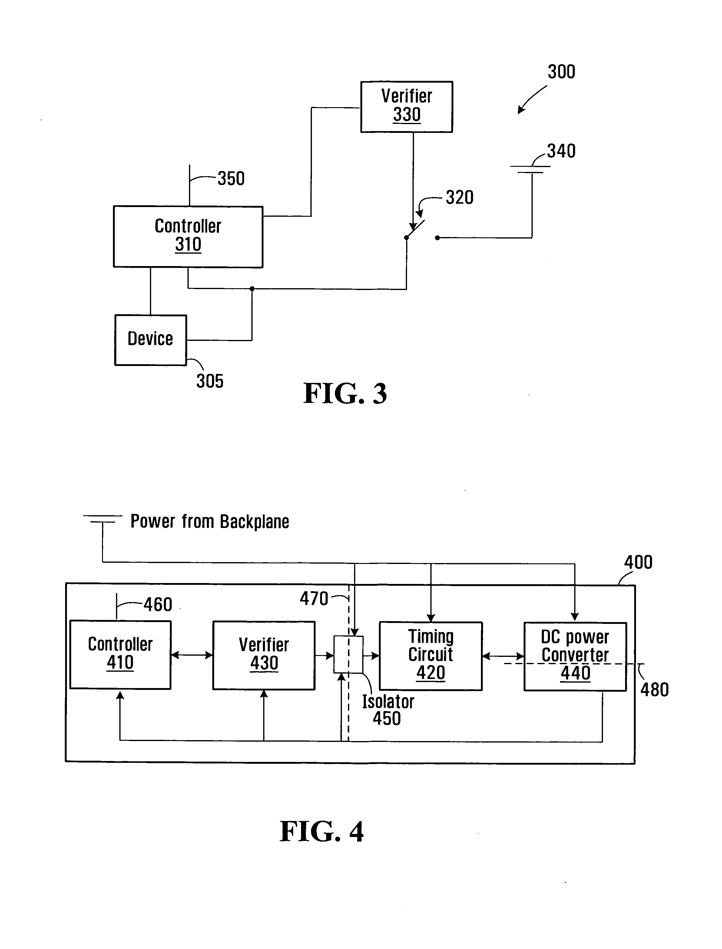
[0012] In some embodiments, the timing circuit is electrically isolated from the device and / or the controller. For example, the timing circuit may be energized by an electrical power source whose voltage is higher than that required to drive the device and / or the controller. Electrical isolation between the device and / or controller and the timing circuit assists in increasing the reliability of the system in completely removing power from the device and / or controller during the power cycle.
[0014] Some embodiments of the apparatus further comprise a verifier or validation circuit for verifying that the command is a valid command for decoupling power from the device and / or controller. The verifier reduces the risk that the controller will initiate a power cycle through a signal that was not intended to cause a power cycle.

Problems solved by technology

However, in some situations, a software reset is insufficient to clear the error, and in this case, personnel need to be dispatched into the field to physically inspect the switching element on sight and resolve the problem.
A drawback of this procedure is that personnel must physically visit the network element site in order to perform a power cycle on the failed line card which is both costly and time consuming.

Method used


Image

  • Power cycle circuit
  • Power cycle circuit
  • Power cycle circuit

Examples


Embodiment Construction

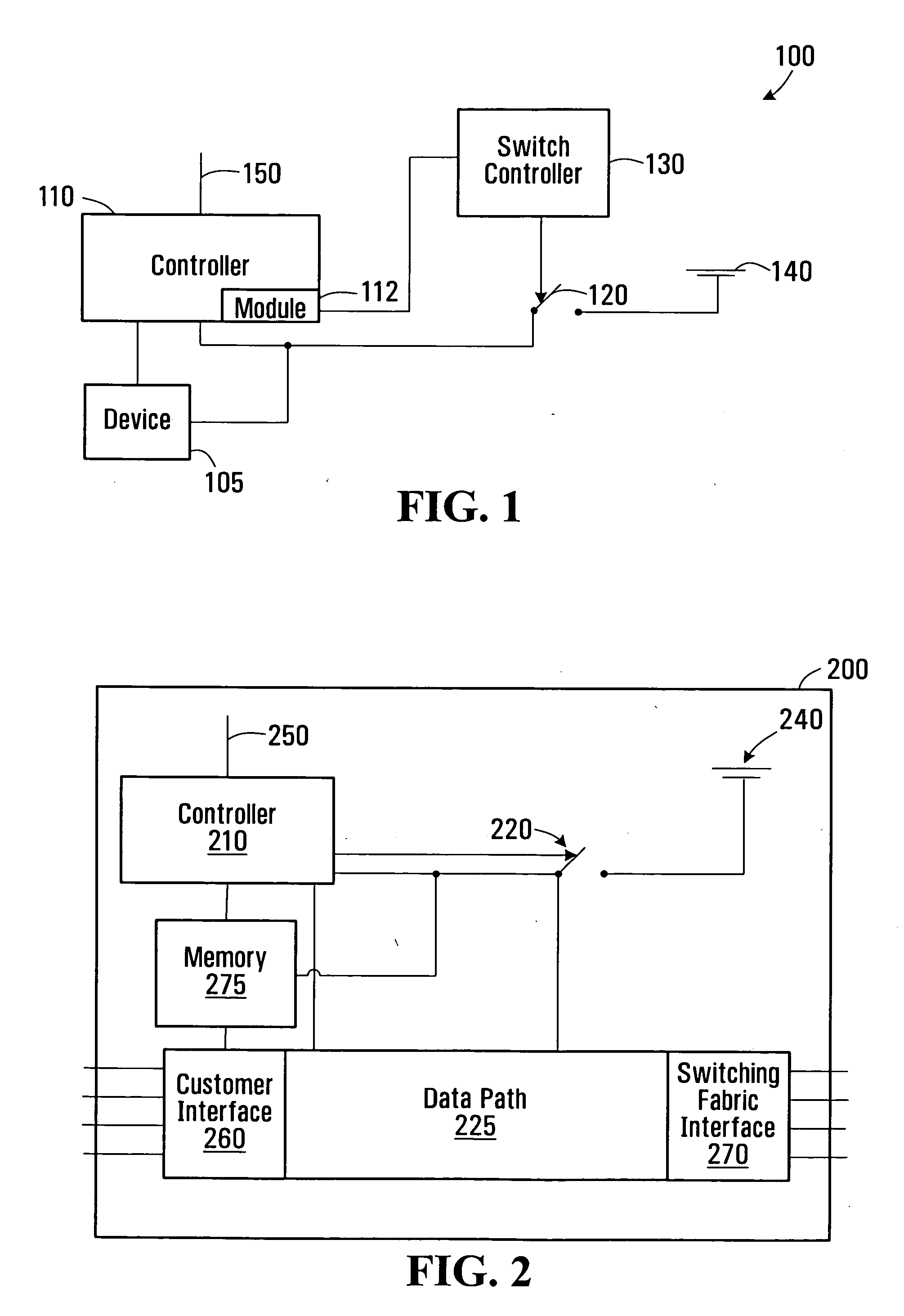
[0039] Referring to FIG. 1, an apparatus 100 in accordance with one embodiment of the present invention, comprises a device 105 and a controller 110 for controlling operation of the device. The device 105 and controller 110 are enabled to operate by electrical power from an electrical power source 140. A switch 120 can couple and decouple the electrical power to and from the device 105 and the controller 110. The controller 110 includes a module 112 for controlling the switch to decouple the electrical power source 140 from the device 105 and the controller 110. The apparatus also includes a switch controller 130, which controls the switch 120 to restore the electrical power from the power source 140 to the device and controller after a predetermined time has elapsed from decoupling the electrical power from the device and the controller.

[0040] Therefore, in operation the module 112 for controlling the switch 120 can issue a command to the switch 120 to decouple the electrical powe...


PUM


Abstract

An apparatus comprises a controller for controlling operation of the apparatus and a switch for switchably coupling electrical power to the controller to enable the controller and apparatus to operate. The controller includes a module for controlling the switch to decouple electrical power from the apparatus, including the controller, and the apparatus further comprises a switch controller for controlling the switch to restore electrical power to the apparatus and controller a predetermined period of time after the switch decouples electrical power therefrom. The apparatus may be embodied in a line card of a communication system and the controller may comprise a control processor for controlling local operations of the line card.

Description

FIELD OF THE INVENTION [0001] The present invention relates to circuits for controlling power cycles, and in particular, but not limited to, circuits for controlling power cycles in communication devices. BACKGROUND [0002] A communication network switch typically comprises a number of line cards having communication ports connected to a communication network for transmitting and receiving communication data to and from the network, and a control processor for controlling local operations of the line card. A control card is also provided for monitoring and managing operation of the line cards. Occasionally, events occur which cause line cards to malfunction or become inoperative, and in some cases line cards can be restored to their operative condition by a software reset which causes the software which controls the card to reboot. However, in some situations, a software reset is insufficient to clear the error, and in this case, personnel need to be dispatched into the field to phys...

Claims


Application Information

Patent Timeline
IPC IPC(8): G06F1/26
CPCH04M19/08
Inventor DOYON, ERICPEARSE, CHARLES ALEXANDERD'ADDONA, TONY
Owner WSOU INVESTMENTS LLC
Learn More