Can lid

a can lid and lid technology, applied in the field of can lids, can solve the problems of difficult to provide favorable transferring performance, difficult to pull up the pull-up part successfully, deterioration of stacking performance, etc., and achieve the effect of reducing preventing the deterioration of the compressive strength of the can lid, and preventing the slant of the riv

Active Publication Date: 2007-09-20
UNIVERSAL CAN CORP
View PDF2 Cites 25 Cited by
  • Summary
  • Abstract
  • Description
  • Claims
  • Application Information

AI Technical Summary

Benefits of technology

[0024] The present invention was made, taking these circumstances into consideration, and it is an object of the present invention to provide a can lid which is capable of having one's finger easily inserted into a gap between the upper surface of the can lid main body and the pull-up part of the tab, and equipped with excellent opening performance, without deteriorating the compressive strength and impact strength of a can lid.

Problems solved by technology

Incidentally, hitherto there has been a problem in that a finger hardly enters into a gap between the upper surface of the can lid main body and the pull-up part of the tab and hence it is difficult to pull up the pull-up part successfully.
When transferring the can lids, a lower surface of a recess for inserting one's finger comes into contact with an upper surface of a tab of the other can lid which is located facing the lower surface so as to form a space between curling parts of the can lids which are adjacent to each other in a stacking direction, i.e. an accordion-like situation, and as a result, stacking performance deteriorates and it becomes difficult to provide favorable transferring performance.
There has been a problem in that if the content is poured from the can in which one can lid has been wound and fastened into the other vessel, then it becomes difficult that the content sparkle in the case in which the content is for example beer.
However, there is a problem in that it is difficult to provide favorable transferring performance and foaming performance, similar to the can lid disclosed in Patent document 1, because the upper surface of the tab of one can lid comes into contact with the lower surface of another can lid which is placed facing the can lid, when transferring the can lid through a tube in the production process of a can lid.
However, in such a constitution, there is a possibility that the tab and the bead come into contact with each other due to the vibration which acts on the can when transferring the can, thereby breaking the main score which demarcates the opening part.
That is, they have formulated a hypothesis that the distance between the pull-up part of the tab and the upper surface of the can lid main body had already decreased in the simplicial can lid before being wound and fastened to the opening of a can body, and hence it was as difficult as ever to insert one's finger into the gap between the upper surface of the can lid main body and the pull-up part of the tab before or after an inner pressure is applied.
However, the can lid has a problem in that the compressive strength and the impact resistance may deteriorate, because part of the secondary-score must be located at a coining part in order to open the part surrounded by the secondary-score.
However, the secondary-score disclosed in Japanese Unexamined Patent Application, First Publication No. 8-164935 is formed in the vicinity of a rivet which is adjacent to the rivet in the upper surface of the can lid main body, and hence the secondary-score may be located in the coining part, thereby it is not possible to securely prevent the deterioration in compressive strength and impact strength of a can lid due to the provision of the secondary-score.
No. 8-11882, and hence it is not possible to securely prevent the deterioration in compressive strength and impact strength of a can lid, similar to Japanese Unexamined Patent Application, First Publication No. 8-164935 above.

Method used


Image

  • Can lid
  • Can lid
  • Can lid

Examples


Embodiment Construction

[0061] An explanation will be given about embodiments of the present invention below, referring to the drawings.

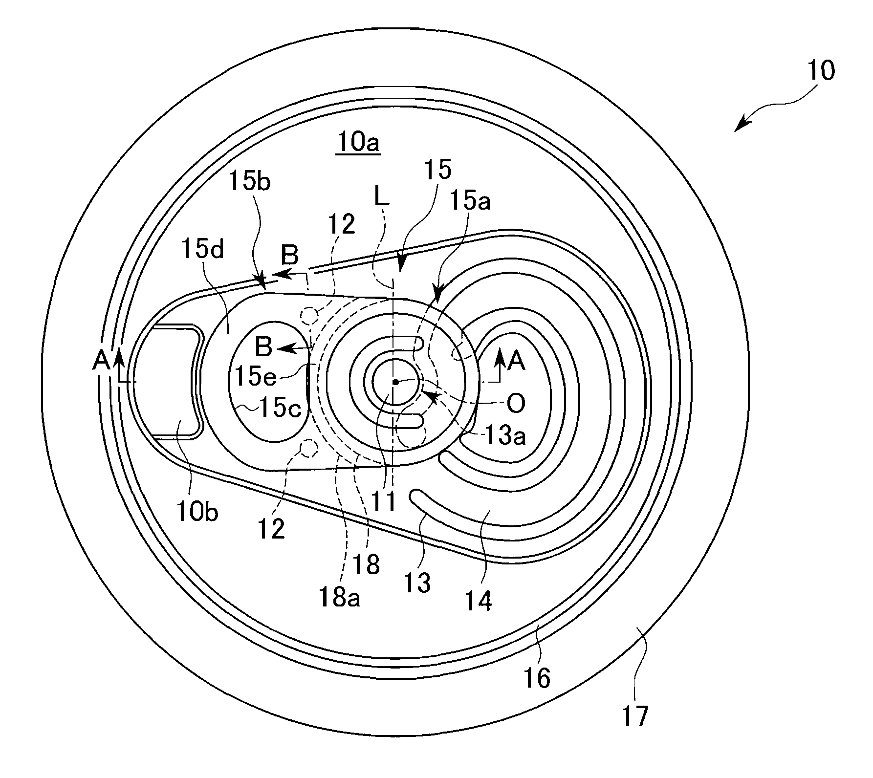
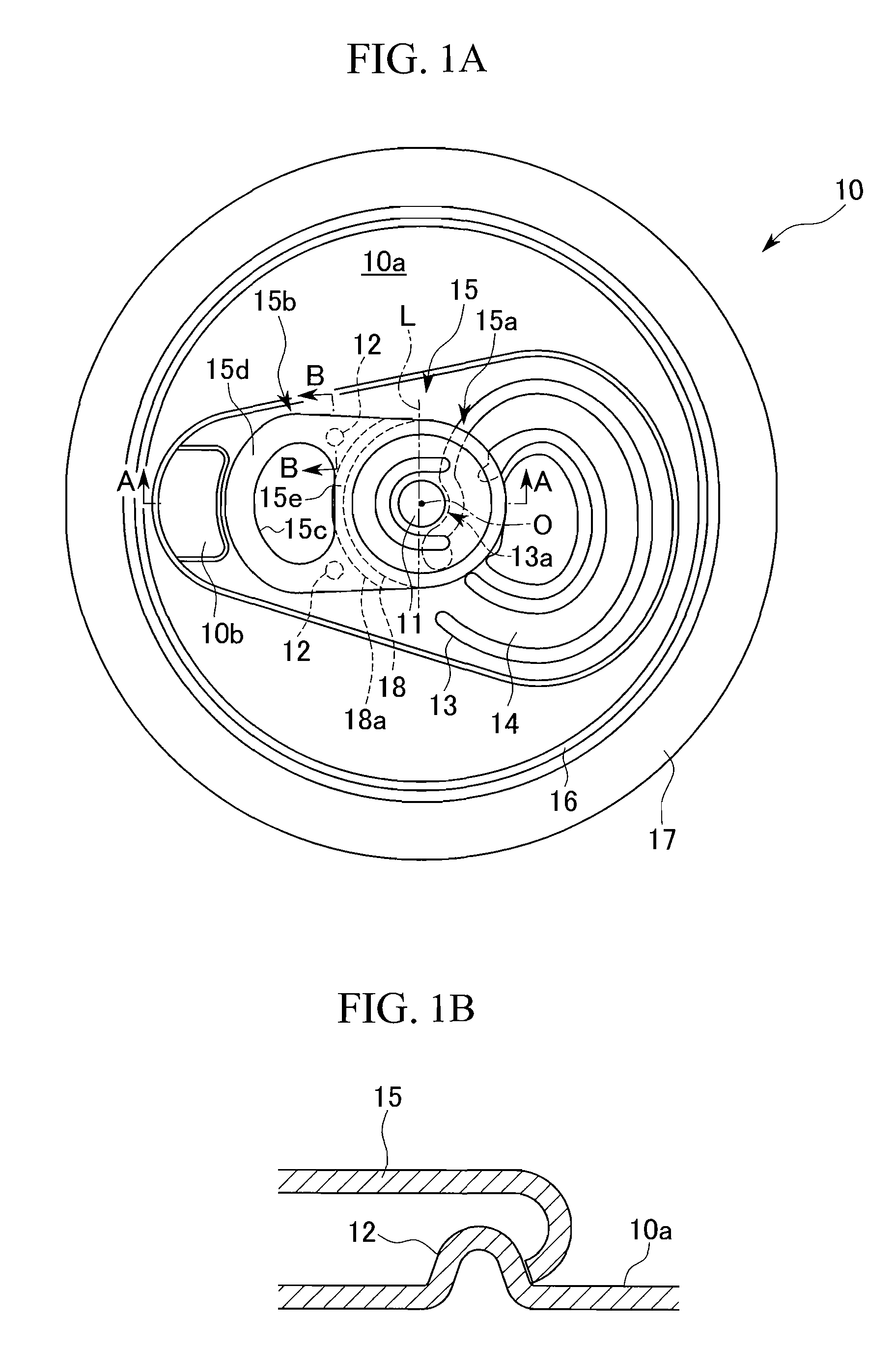
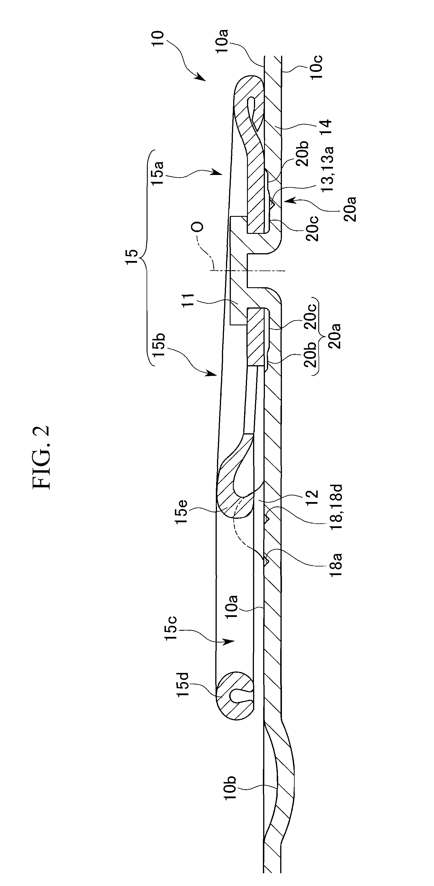
[0062] FIGS. 1 to 4 are drawings each of which shows the schematic constitution of a can lid illustrated as an embodiment of the present invention.

[0063] This can lid is made of pure aluminum or aluminum alloy, and is constituted from a rivet 11 and a dimple 12 which are formed gibbously and upwardly, and an opening part 14 demarcated by a main score 13, on a can lid main body 10a (referred to as “upper surface 10a”, below) 10a of a can lid main body 10, in which the dimple 12 and the opening part 14 are arranged so as to be opposed to each other across the rivet 11. That is, the dimple 12 is arranged on the opposite side to the opening part 14 with the rivet 11 therebetween, and a tab 15 which is fixed to the rivet 11 in such a way that one end thereof 15a overlaps the opening part 14, whereas the other end thereof 15b overlaps the dimple 12.

[0064] Moreover, on the per...


PUM


Abstract

In this can lid, a rivet-slanting inhibitor which flows a metal of the can lid main body located between the rivet to the rivet side thereby correcting or preventing the slanting of the rivet is formed on a location in an opposite area which is opposed to an opening part across the rivet except for the coining part.

Description

CROSS REFERENCE TO PRIOR APPLICATIONS [0001] This is a U.S. national phase application under 35 U.S.C. § 371 of International Patent Application No. PCT / JP2005 / 017410 filed Sep. 21, 2005, and claims the benefit of Japanese Application No. 2004-286726 filed Sep. 30, 2004, both of them are incorporated by reference herein. The International Application was published in Japanese on Apr. 6, 2006 as International Publication No. WO 2006 / 035653 under PCT Article 21(2). TECHNICAL FIELD [0002] The present invention relates to a can lid which is wound and fastened to an opening of a can body. BACKGROUND ART [0003] A can lid of this type generally consists of a rivet and dimples which are gibbously and upwardly shaped, an opening which is demarcated by a main score and arranged across the rivet for the dimples, and a tab which is fixed to the rivet such that one end part thereof overlaps the opening and the other end thereof overlaps the dimples on an upper surface of the can lid main body. O...

Claims


Application Information

Patent Timeline
Patent Type & Authority Applications(United States)
IPC IPC(8): B65D17/34
CPCB65D17/165B65D2517/0014B65D17/24B65D17/4012B65D17/404Y10S220/906B65D17/02B65D17/28
Inventor SHINGURYO, TAKUROTAGUCHI, KAZUHIROSHIBATA, KENICHIITO, HIDEKI
Owner UNIVERSAL CAN CORP
Why Eureka
Try Eureka