Unlock instant, AI-driven research and patent intelligence for your innovation.

Comb structure fabrication methods and systems

Inactive Publication Date: 2007-09-20
HONEYWELL INT INC
View PDF2 Cites 4 Cited by
  • Summary
  • Abstract
  • Description
  • Claims
  • Application Information

AI Technical Summary

Benefits of technology

[0004] The present invention provides a method of manufacturing a comb structure on a MEMS device which can achieve much smaller tolerances between opposing teeth of the comb structure than current manufacturing methods.

Problems solved by technology

One limitation of current methods of manufacturing the comb structure of the Leonardson accelerometer is the practice of manufacturing the proof mass and the cover plate separately, each including tooth-type electrodes, and then mechanically assembling the proof mass and the cover plate.

Method used


Image

  • Comb structure fabrication methods and systems
  • Comb structure fabrication methods and systems
  • Comb structure fabrication methods and systems

Examples


Embodiment Construction

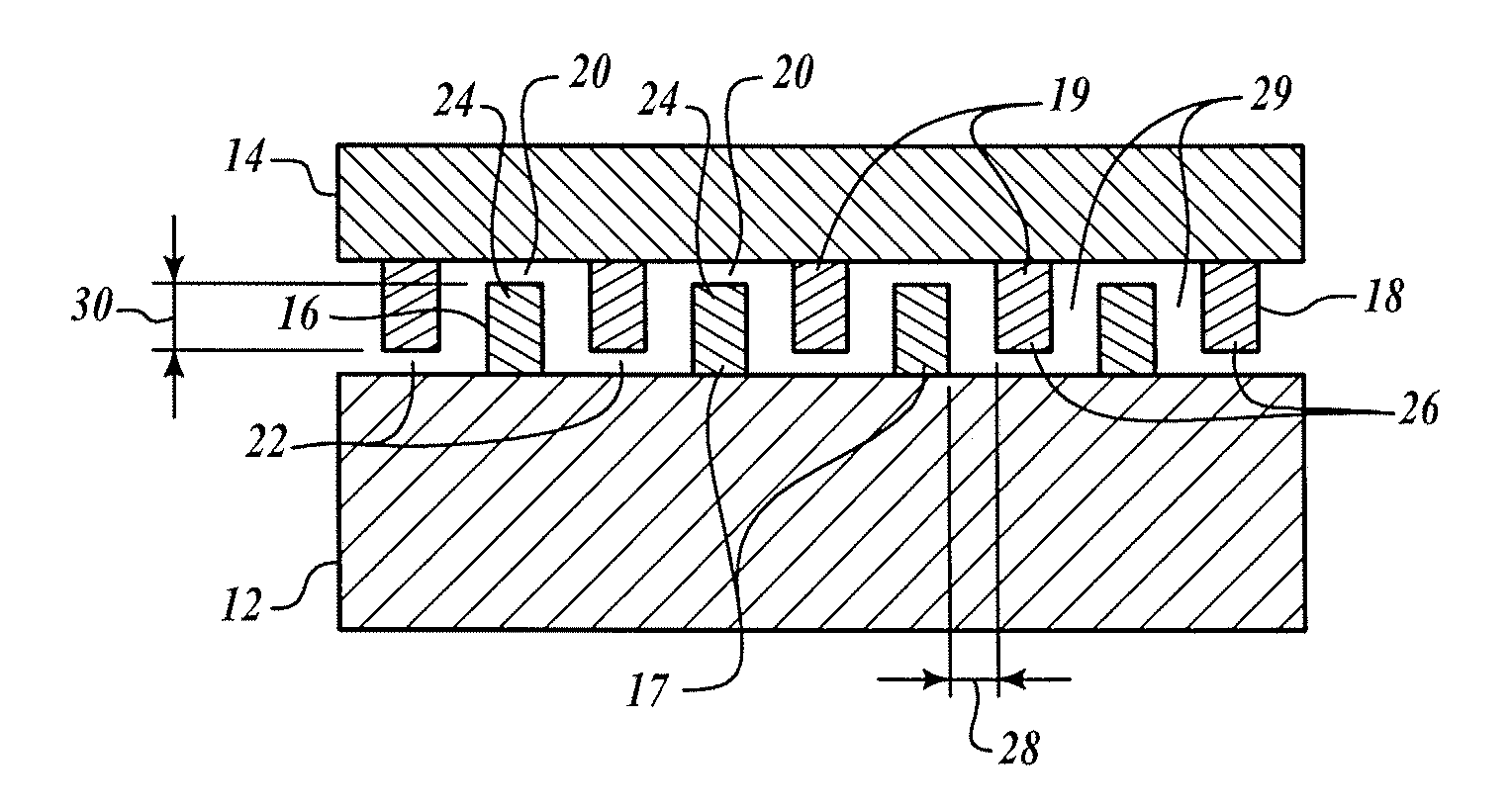
[0012]FIG. 1 shows a cross-section view of a finished comb structure 10 manufactured according to a method of the present invention. The structure 10 includes a first substrate layer 12 and a second substrate layer 14. By way of example and without loss of generality, the substrate layers 12, 14 may be silicon wafers. The first substrate layer 12 includes discretely formed first teeth 16 attached to the first substrate layer 12 at a first proximal end 17, and the second substrate layer 14 includes discretely formed second teeth 18 attached to the second substrate layer 14 at a second proximal end 19. First and second teeth 16, 18 have associated first and second recesses 20, 22 between a distal end 24, 26 of each tooth 16, 18 and the opposite substrate layer 14, 12, respectively. The structure additionally includes a separation distance 28 and spaces 29 between adjacent teeth 16, 18 and an overlap distance 30 between adjacent teeth 16, 18.

[0013]FIGS. 2A-2H illustrate the steps perf...


PUM


Abstract

A method of manufacturing a vertical comb structure for a micro electromechanical (MEMS) device. Tooth structures are formed on a first wafer. A second wafer is then bonded to the tooth structures of the first wafer. The tooth structures are then released to form a comb structure. Forming the tooth structures on the first wafer includes using oxidation, photolithography, etching, epitaxy, and chemical and mechanical polishing to create the tooth structures on the first wafer.

Description

BACKGROUND OF THE INVENTION [0001] The manufacture of microelectromechanical system (MEMS) devices is generally well-known, and there are numerous devices used in different applications and numerous methods of making those devices. An example of a method of manufacturing a MEMS device is contained in U.S. Pat. No. 6,925,710 titled “METHOD FOR MANUFACTURING MICROELECTROMECHANICAL COMBDRIVE DEVICE” TO Scalf et al., herein incorporated by reference. An example of a MEMS device is contained in U.S. Pat. No. 6,705,166 titled “SMALL SIZE, HIGH CAPACITANCE READOUT SILICON BASED MEMS ACCELEROMETER” to Leonardson, herein incorporated by reference. [0002] The Leonardson accelerometer provides an inexpensive force measurement device having high pick-off sensitivity in a high-G input range which can operate in a high-G shock environment by providing a capacitance pick-off force sensor having a proof mass with spaced-apart tooth-type electrodes (i.e., a comb structure) that is suspended by an an...

Claims


Application Information

Patent Timeline
IPC IPC(8): H01L29/82H01L29/84
CPCB81B2201/0235B81B2201/033B81C2201/019B81C1/00484B81B2203/0136
Inventor YU, LIANZHONG
Owner HONEYWELL INT INC