Frame for heavy-duty vehicles

a technology for heavy-duty vehicles and frames, applied in the direction of vehicle springs, vehicle components, resilient suspensions, etc., can solve the problems of different welding of aluminum components, potentially more difficult than welding of steel components, and potential for weaker connections, so as to reduce potential damage and efficient distribute loading forces

Inactive Publication Date: 2007-09-20
HENDRICKSON USA L L C
View PDF14 Cites 23 Cited by
  • Summary
  • Abstract
  • Description
  • Claims
  • Application Information

AI Technical Summary

Benefits of technology

[0016]One objective of the present invention is to provide heavy-duty vehicle primary frames and subframes that are lighter in weight than prior art subframes having steel components, with connections between selected components that are stronger than connections established by welding the components.
[0017]Another objective of the present invention is to provide heavy-duty vehicle primary frames and subframes that efficiently distribute loading forces.
[0018]Yet another objective of the present invention is to provide heavy-duty vehicle primary frames and subframes that reduce potential damage from extreme events

Problems solved by technology

Second, local, state and / or national road and bridge laws typically set a maximum weight limit for a trailer load, which includes the weight of the trailer and the payload carried on or in the trailer.
However, certain characteristics of aluminum, such as high thermal conductivity and a low melting point, make the welding of aluminum components different, and potentially more difficult, than the welding of steel components.
In addition, aluminum components that are welded together may exhibit fatigue at the weld area, thereby potentially creating a weaker connection when compared to steel components that are welded together.
The potential for a weaker connection may become a concern at the interface between the main members and the hangers, and potentially at any interface between the cross members and the hangers.
More particularly, loads or forces acting on the axle / suspension system, such as brake loads, fore-aft loads, side loads, curbing loads, vertical loads and torsional loads, tend to cause the hanger to rock or move fore-to-aft and side-to-side.
Such movement of the hanger highly stresses the rigid attachment of the hanger to the main member and potentially any rigid attachment of the hanger to the cross member, which may cause a potentially less-than-optimal weld to fail.
Thus, the use of aluminum components, which may not facilitate a welded connection that is as strong as a weld between steel components, may undesirably fail.
However, in the prior art, it has been difficult to attach the hanger to the main member and / or cross member using bolts in a manner which enables adequate distribution among the bolts of the different loading forces that act on the axle / suspension system and thereby achieve a satisfactory fatigue life of the slider box components
When a vehicle encounters an extreme event, a vertical crush force is produced which potentially can cause significant damage to the slider box.
A side force may also be produced if the impact is on a single wheel, which would cause the beam to pull back and sideways, causing the hanger to twist.
These impacts could damage, or in an extreme case, cause a slider box main member and / or one or more of the attached cross members to fail, in either instance eventually requiring replacement, which is costly and time-consuming.
This design of a typical slider tandem causes many heavy-duty vehicles containing such slider tandems to be out of service for extended periods of time after such extreme events until the entire slider box can be replaced.

Method used


Image

  • Frame for heavy-duty vehicles
  • Frame for heavy-duty vehicles
  • Frame for heavy-duty vehicles

Examples


first embodiment

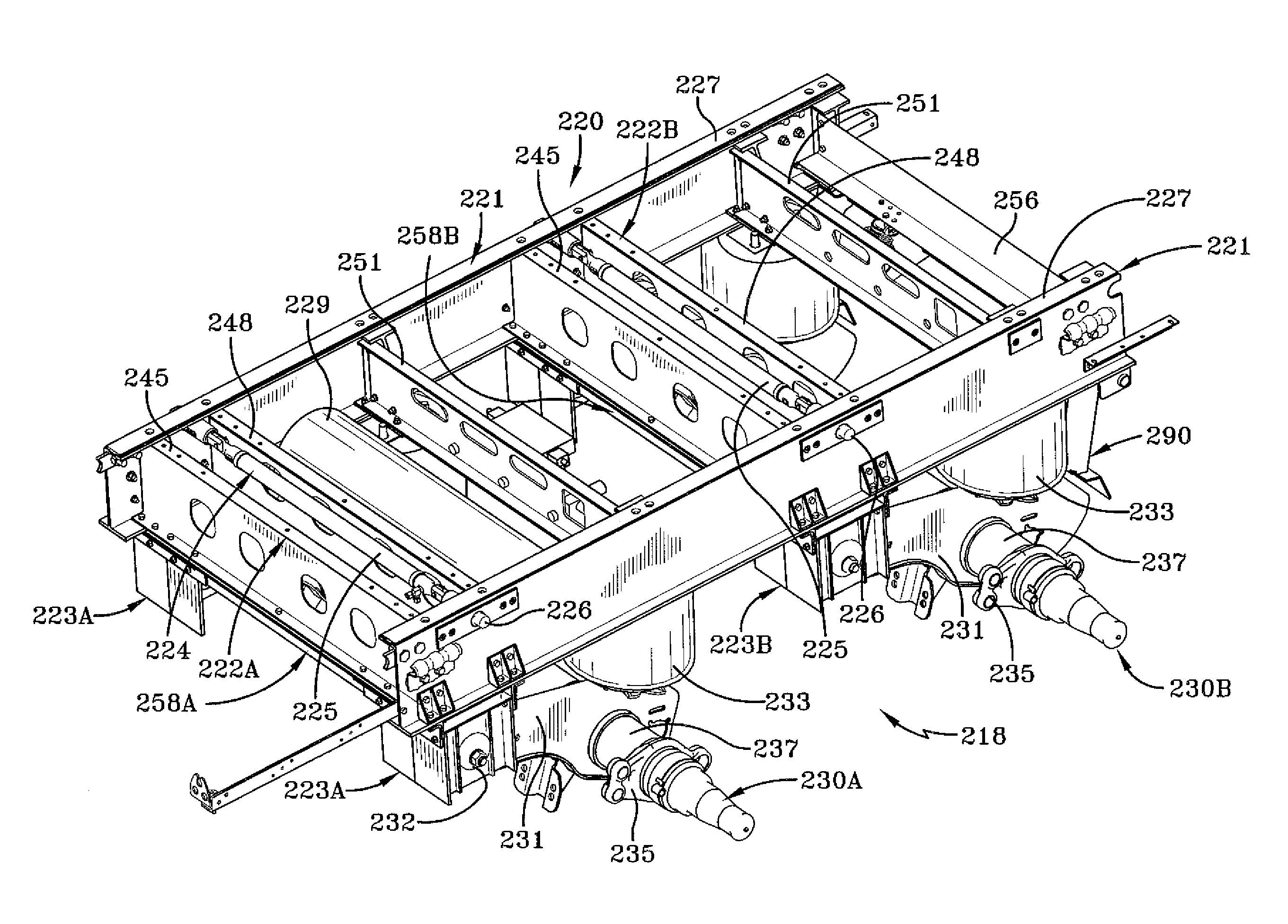
[0059]With additional reference to FIGS. 5 and 6, first embodiment slider box 220 supports front and rear axle / suspension systems 230A,B, forming slider tandem 218 Inasmuch as axle / suspension systems 230A,B are suspended from slider box 220, but do not form an integral part thereof, only the major components of the system will be cited for aiding in the description of the environment in which the slider box operates. Each axle / suspension system 230A,B includes a suspension beam 231 which is pivotally mounted on each respective hanger 223A,B in a usual manner via a bushing assembly 232. An air spring 233 is suitably mounted on and extends between the upper surface of the rearwardmost end of suspension beam 231 and main member 221 at a location directly beneath a rear cross member 251 of each cross member set 222A,B. A shock absorber 234 extends between and is mounted on suspension beam 231 and force distribution assembly 258A,B, as will be described in greater detail below. Component...

second embodiment

[0088]In order to enable second embodiment slider box 320 to interface with other structures associated with the heavy-duty vehicle (not shown) as well as for other purposes, the front and rear open ends of each main member 321 preferably receive an end bracket 362

[0089]Second embodiment slider box 320 of the present invention provides a robust structure that is interconnected by mechanical fasteners, thereby reducing the potential for failure of welds in high-stress areas. Moreover, the use of lower cross member 354A,B under main members 321 enables forces encountered by axle / suspension system 230A,B (FIG. 5) to generally travel up each respective hanger 323A,B and across the lower cross member for distribution across to the opposing main member More particularly, the attachment of lower cross members 354A,B to respective hangers 323A,B below main members 321 interrupts the transmission of forces from bushing assembly 232 (FIG. 5) up the hangers to the interface between the hangers...

third embodiment

[0104 slider box 400 of the present invention provides a robust structure that is interconnected by mechanical fasteners, thereby reducing the potential for failure of welds in high-stress areas. Moreover, the use of force distribution assembly 402A,B under main members 221 enables forces encountered by axle / suspension system 230A,B (FIG. 5) to generally travel up each respective hanger 406A,B and across lower cross members 270 for distribution across to the opposing main member. More particularly, the attachment of lower cross members 270 of force distribution assembly 402A,B to respective hangers 406A,B below main members 221 interrupts the transmission of forces from bushing assembly 232 (FIG. 5) up the hangers to the interface between the hangers and the main members, thereby reducing the moment arm along which the loading forces act, which in turn reduces the magnitude of the resultant forces. In this manner, forces encountered by the system are distributed among main members 2...


PUM


Abstract

A frame for a heavy-duty vehicle includes a pair of spaced-apart and longitudinally-extending main members. At least two cross members extend between and are attached to the main members. Each one of at least a pair of hangers is attached to and depends from a respective one of the main members for suspending an axle / suspension system from the frame. A force distribution assembly is attached to the main members and the hangers and includes a component that deforms or shears in an extreme event. The force distribution assembly extends perpendicularly between the main members and interrupts the transmission of forces encountered by the axle / suspension system that move through each one of the hangers to its respective main member, and redirects at least a portion of such forces across said force distribution assembly and into the other one of the main members.

Description

CROSS-REFERENCE TO RELATED APPLICATION[0001]This application claims the benefit of U.S. Provisional Patent Application Ser. No. 60 / 782,803, which was filed on Mar. 16, 2006.BACKGROUND OF THE INVENTION[0002]1. Technical Field[0003]The invention relates to heavy-duty vehicles, and in particular, to frames and subframes for heavy-duty vehicles. More particularly, the present invention is directed to frames and subframes for heavy-duty vehicles which include selected components that are bolted together in a manner that provides efficient distribution of forces, and include components for absorbing energy in an extreme event during vehicle operation.[0004]2. Background Art[0005]Heavy-duty vehicles that transport cargo, for example, tractor-trailers or semi-trailers, and straight trucks such as dump trucks, typically include leading or trailing arm suspension assemblies that connect the axles of the vehicle to the frame of the vehicle. In some heavy-duty vehicles, the suspension assemblie...

Claims


Application Information

Patent Timeline
Patent Type & Authority Applications(United States)
IPC IPC(8): B62D21/00B60G9/00
CPCB60G7/02B60G9/003B60G11/27B60G2200/31B60G2202/15B60G2202/152B62D21/186B60G2300/026B60G2300/042B60G2300/40B62D21/02B62D21/03B60G2204/15
Inventor RAMSEY, JOHN EDWARD
Owner HENDRICKSON USA L L C
Why Eureka
Try Eureka