Demodulation method of resolver output position signal

Inactive Publication Date: 2007-09-20
HIWIN MIKROSYST
View PDF3 Cites 15 Cited by
  • Summary
  • Abstract
  • Description
  • Claims
  • Application Information

AI Technical Summary

Benefits of technology

[0010] The primary objective of the present invention is to solve the aforementioned problems by providing a demodulation method of a resolver output position signal, which can demodulate the position signal and make the feedback signal accurately readable by the driver, thus improving the resolution. To achieve this objective, the demodulation method of a resolver output position signal in accordance with the p

Problems solved by technology

However, the disadvantage of this method is in that the distorted waveform (as shown in FIG. 4) cannot be restored, and thus an error signal w

Method used


Image

  • Demodulation method of resolver output position signal
  • Demodulation method of resolver output position signal
  • Demodulation method of resolver output position signal

Examples


Embodiment Construction

[0022] Referring to FIGS. 4-10, which show a preferred embodiment of the present invention, and the embodiment is intended for illustrative purposes only and not as a limitation on the invention.

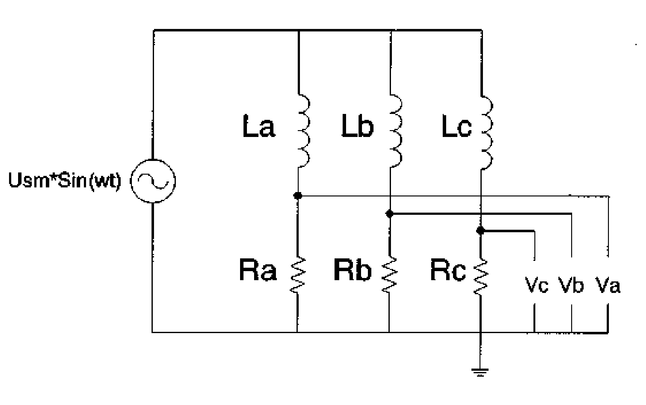
[0023] Referring firstly to FIG. 5, a demodulation method in accordance with the present invention comprises the steps of: inputting an excitation signal; using a push-pull amplifier circuit to increase fan-out; using a voltage regulator to adjust the amplitude of the signal outputted from the resolver to the same level, for improving resolution; modulating with a subtracter; amplifying the signal with an amplifier circuit for providing signal waveform readable by the RDC or the controller.

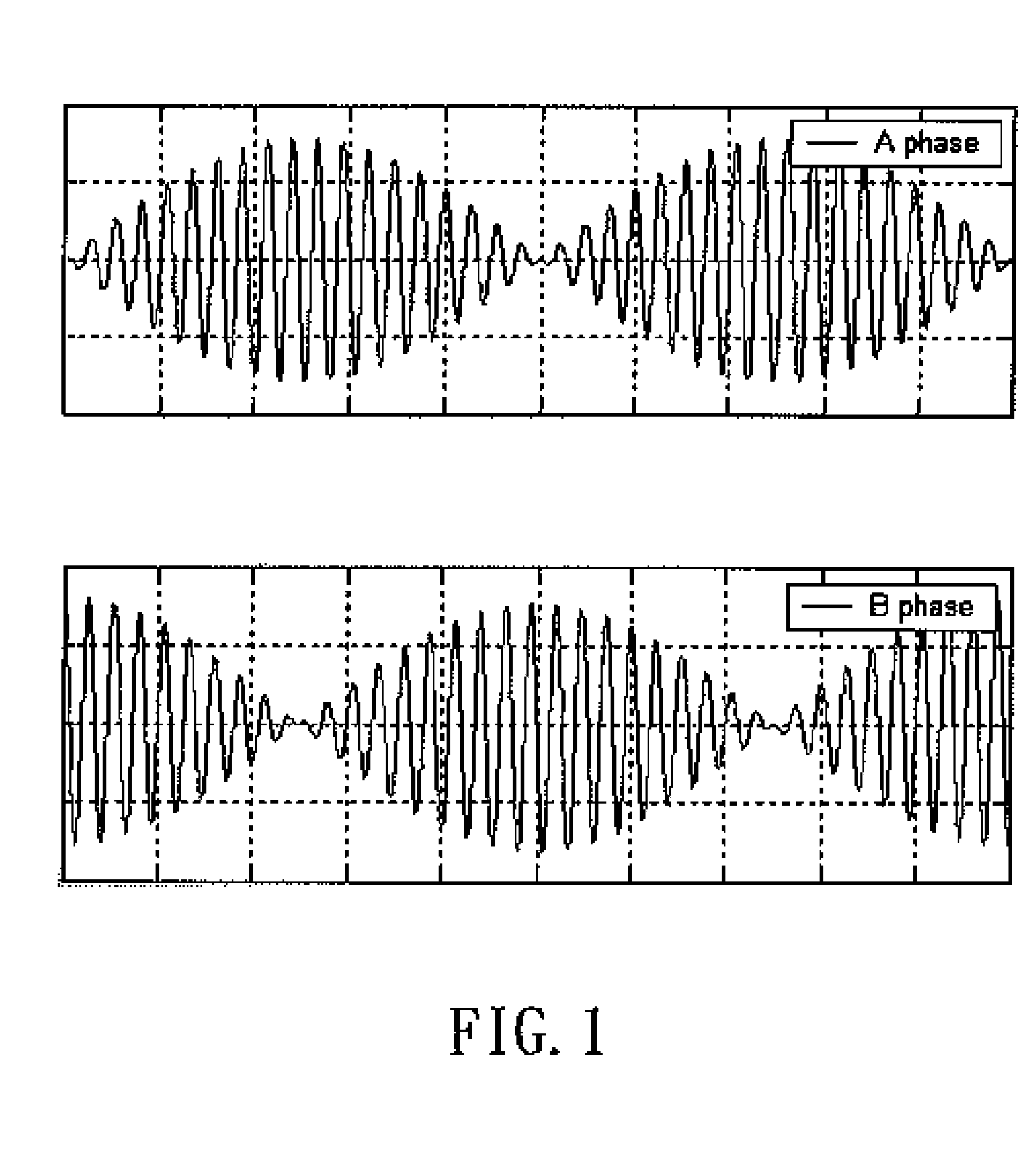
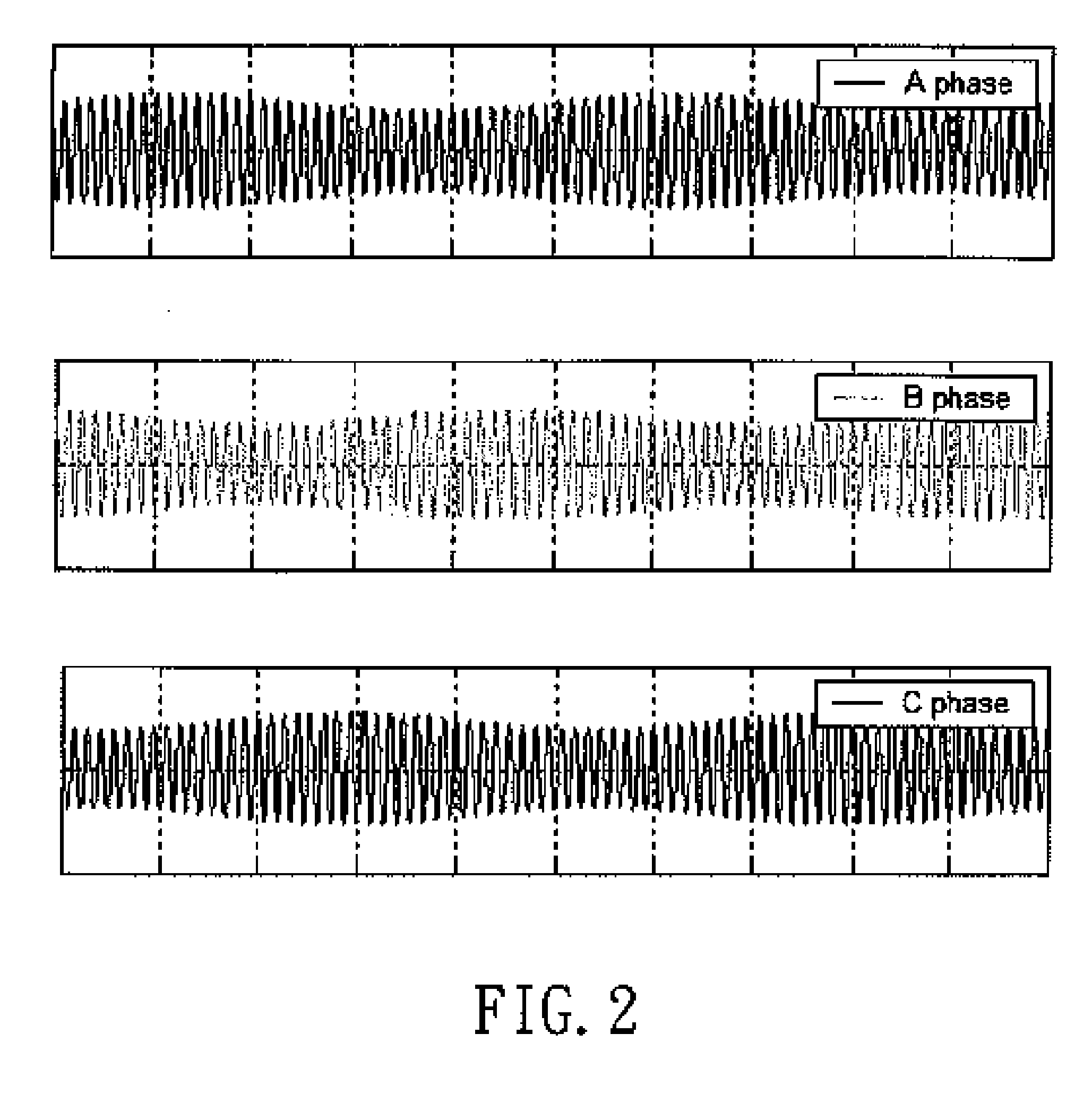
[0024] In addition, the resolver in this embodiment is 4-phase resolver with phase shifts of A (O degree), B (90 degrees), C (180 degrees) and D (270 degrees) for example, which output signals as illustrated in FIGS. 6-9, and the signals are represented by the following equations:

Va=Ua (1+k1 sin θ+k2 si...


PUM


Abstract

A demodulation method of a resolver output position signal comprises the steps of: inputting an excitation signal, using a push-pull amplifier circuit to increase fan-out; using a voltage regulator to adjust the amplitude of resolver signals to the same level, for improving resolution; modulating with a subtracter; amplifying the signal with an amplifier circuit for providing signal waveform readable by a resolver to digital converter or a controller.

Description

BACKGROUND OF THE INVENTION [0001] 1. Field of the Invention [0002] The present invention relates to a demodulation of the position signal outputted from a resolver, and more particularly to a demodulation method of the resolver output position signal, which can demodulate the position signal and make the feedback signal accurately readable by the driver, thus improving the resolution. [0003] 2. Description of the Prior Art [0004] The working principle of a rotary motor is that the current flows to the stator via a transistor 3-phase inverter and a pulse width modulator (PWM), producing a rotating magnetic field, and then the rotating magnetic field will interact with the permanent magnet of the rotor and generate a torque. The intention of an electronic commutator is to enable the stator generated magnetic field to be maintained in a vertical direction with respect t to the magnetic field of the rotor's permanent magnet, so as to produce a maximum torque. And this intension should ...

Claims


Application Information

Patent Timeline
IPC IPC(8): H02P7/06
CPCG01D5/2093
Inventor LIU, MING-SHINGSU, YI-CHENG
Owner HIWIN MIKROSYST
Why Eureka
Try Eureka