Thermal sensor and method

a technology of thermocouplers and sensors, applied in the field of electromechanical devices, can solve problems such as microprocessor overheating and catastrophic failure of microprocessors

Inactive Publication Date: 2007-09-20
INTEL CORP
View PDF5 Cites 45 Cited by
  • Summary
  • Abstract
  • Description
  • Claims
  • Application Information

AI Technical Summary

Problems solved by technology

Without the corrective action, the microprocessor may overhe

Method used


Image

  • Thermal sensor and method
  • Thermal sensor and method
  • Thermal sensor and method

Examples


Embodiment Construction

[0015] In the following description, for purposes of explanation, numerous details are set forth in order to provide a thorough understanding of the disclosed embodiments of the present invention. However, it will be apparent to one skilled in the art that these specific details are not required in order to practice the disclosed embodiments of the present invention. In other instances, well-known electrical structures and circuits are shown in block diagram form in order not to obscure the disclosed embodiments of the present invention.

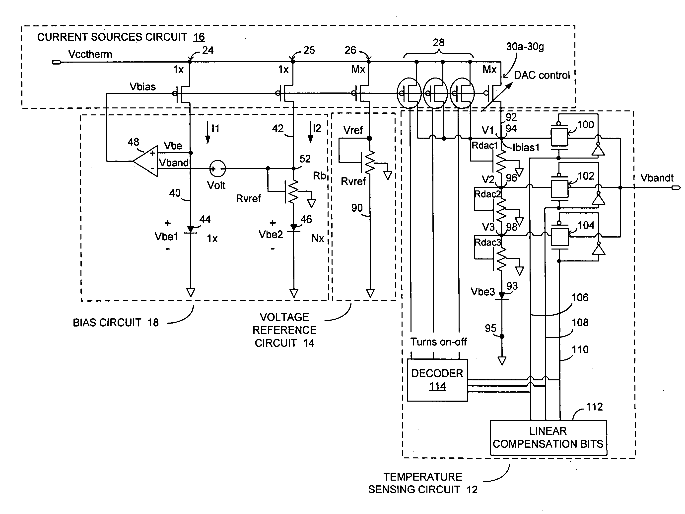
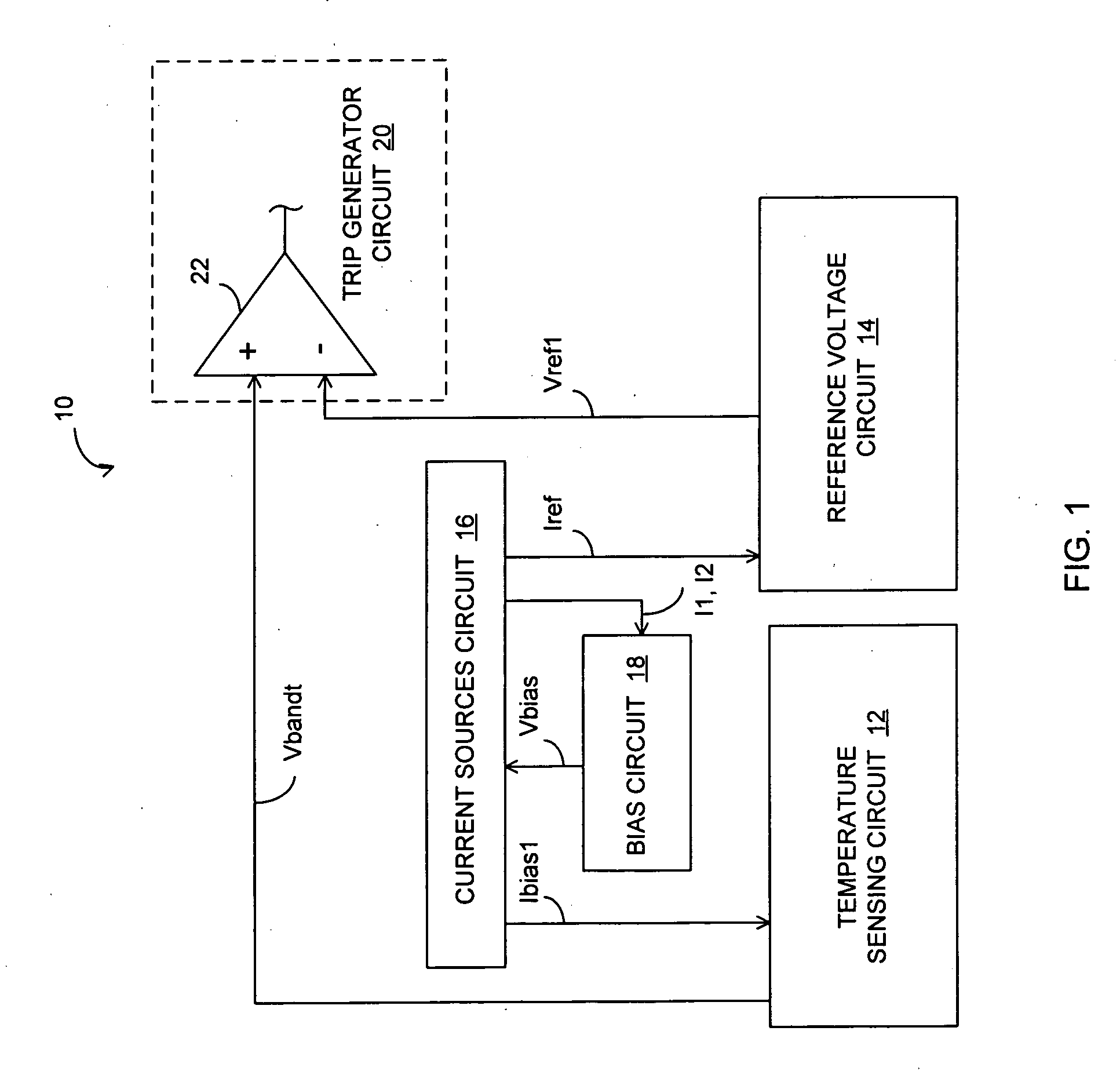
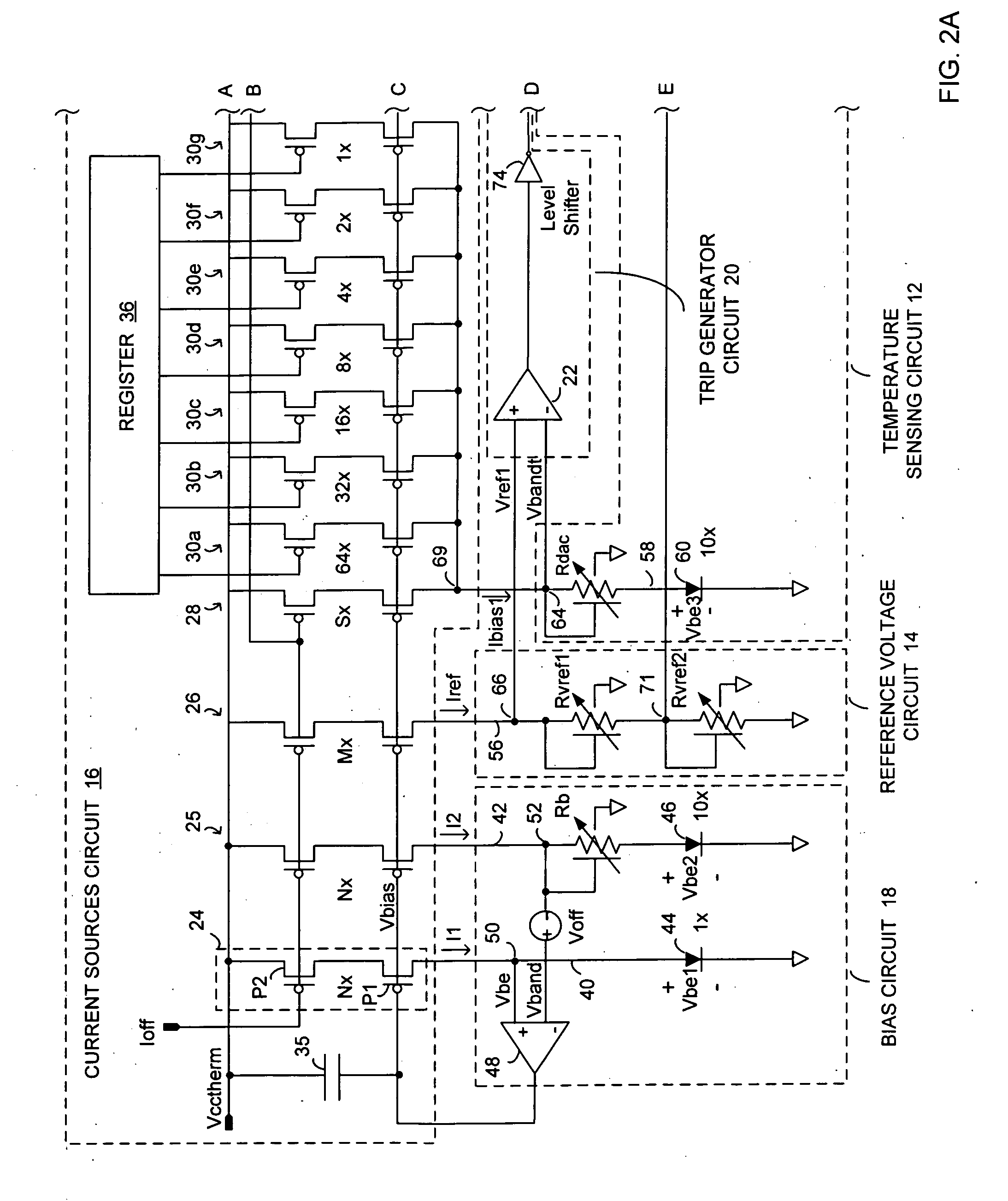
[0016] Referring to FIG. 1, there is illustrated a thermal sensor 10, according to various embodiments of the present invention. In one embodiment, the thermal sensor 10 may include a temperature sensing circuit 12 to monitor and measure a temperature of an integrated circuit (“circuit temperature”) and to generate at least one adjustable temperature-indicating voltage signal Vbandt that changes with the circuit temperature; and a reference voltage ...


PUM


Abstract

In one embodiment, an apparatus is constituted with a temperature sensing circuit adapted to be coupled to a current sources circuit, and configured to measure a circuit temperature and to generate a temperature-indicating signal in response to the circuit temperature and an adjustable current output by the current sources circuit; a reference voltage circuit to be coupled the current sources circuit and configured to provide a reference signal in response to a reference current output by the current sources circuit; and a trip generator circuit coupled to the temperature sensing circuit and the reference voltage circuit and configured to generate a trip point signal if a difference between the reference and the temperature-indicating signals indicates that a threshold circuit temperature has been reached or exceeded.

Description

BACKGROUND [0001] 1. Technical Field [0002] Embodiments of the present invention are related to the field of electronic devices, and in particular, to thermal sensors. [0003] 2. Description of Related Art [0004] A thermal sensor may be used, for example, to monitor a temperature of a microprocessor. When the measured temperature exceeds a predetermined temperature threshold, the thermal sensor may alert circuitry of the microprocessor so that corrective action (throttling back or shutting down the microprocessor, for example) may be taken to reduce the temperature. Without the corrective action, the microprocessor may overheat and catastrophic failure of the microprocessor may occur. [0005] Typically, thermal sensors used with microprocessors include a diode and temperature measuring circuitry. The thermal sensor may be directly attached to a substrate (e.g., heat sink) of the microprocessor by way of a thermocouple or the diode may be embedded in the integrated circuits of the micr...

Claims


Application Information

Patent Timeline
IPC IPC(8): H01L35/00G01K1/08H01H47/26
CPCG01K7/01G01K3/005
Inventor DUARTE, DAVID E.
Owner INTEL CORP
Why Eureka
Try Eureka