
Magnetic encoder

a technology of magnetic encoder and encoder plate, which is applied in the field of magnetic encoder, can solve the problems of low magnetic force, inferior working property and moldability of rare earth magnetic materials, and high cost, and achieves the effects of strong magnetic characteristic, superior handling ability, and small magnetic for

Inactive Publication Date: 2007-09-20
UCHIYAMA MFG
View PDF9 Cites 0 Cited by
  • Summary
  • Abstract
  • Description
  • Claims
  • Application Information

AI Technical Summary

Benefits of technology

[0009] The inventors of the present invention have carefully examined and carried out many magnetic characteristic tests. The object of the present invention is to provide a magnetic encoder which has a strong magnetic characteristic, superior handling ability, and possibility in the price.
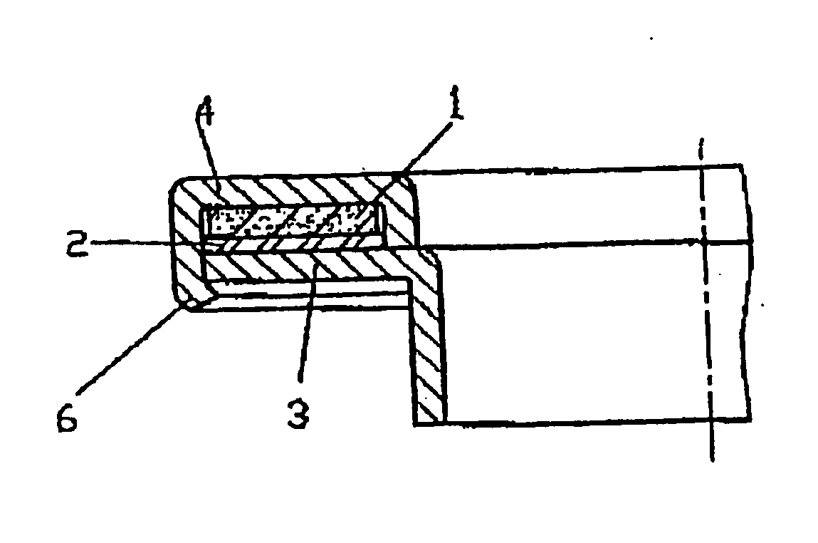
[0010] Still further object of the present invention is to provide a magnetic encoder which is easily fitted to a reinforcing ring even when a magnetic ring is not a unitary magnetic body but is molded by mixing a binder in a magnetic powder and which has no fear of causing gap, distortion, and deformation even when there is the difference of the coefficient of thermal expansion between the magnetic ring and the reinforcing ring and has no fear of damage resulted by contamination of foreign material.
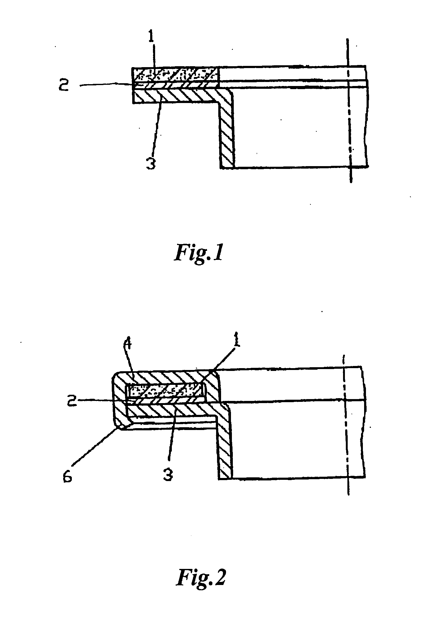
[0012] Silicone sealant with elasticity may be preferably used as the adhesive for fixing the magnetic ring into the reinforcing ring. Such an adhesive has a cushion ability and absorbs the difference of the coefficient of thermal expansion when the difference between the magnetic ring and the reinforcing ring is large, thereby preventing generation of gap, distortion and deformation.
[0014] According to the above-mentioned magnetic encoder, the magnetic ring is fitted to the reinforcing ring by a crimp in place of using the above-mentioned adhesive. Therefore, its production is facilitated while obtaining the same effect of the above-mentioned one aspect of the present invention without using the adhesive.
[0015] In both above-mentioned aspects of the present invention, the magnetic ring may be a single magnetic body or a plastic magnet which is formed of a composite substance in which a binder such as rubber or resin is mixed with a magnetic powder such as ferrite. The magnetic ring made of a single magnetic body is easily produced, has high magnetic force, easily produces a magnetic field, has enough strength, and is highly superior in its handling. Therefore, a magnetic encoder with large pulse generation ability can be provided at a low price and its strong magnetic force makes the gap between the magnetic encoder and a sensor larger, so that its assembly tolerance is roughly determined. As a result, the magnetic encoder will be made smaller and more compact and its high productivity and low cost can be achieved.
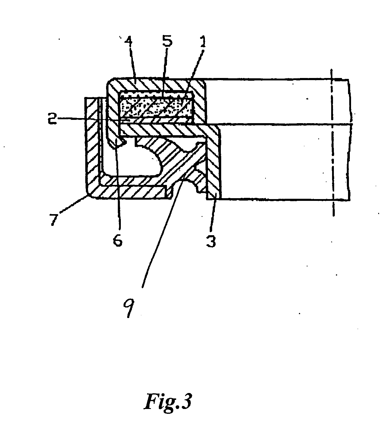
[0017] According to other aspect of the present invention, a magnetic ring is covered with a protective cover made of a nonmagnetic material and the protective cover is fitted to the reinforcing ring by crimping or is fixedly engaged so as to join each other. Therefore, without using an adhesive and without giving the magnetic affect on the magnetic sensor, the magnetic ring is protected from being contact with external factor or colliding.

Problems solved by technology

Whereas, for example, a magnetic material comprised of rare earth is inferior in kneading working property and moldability and requires high cost, so that it is not suitable to be mixed with a rubber material and it is not generally used.
The magnetic encoder formed by being mixed with the ferrite and vulcanized and glued is superior in moldability, but has small magnetic force and is not uniform in magnetic state density because of orientation of magnetic powder.
Therefore, there arise problems such that the rubber property is remarkably deteriorated and its production takes a lots of labor because the above mentioned magnetic encoder is vulcanized and glued in a mold.
Further, complicated site methods are required such that many kinds of ferrite are blended or some extra process of molding are added in order to alleviate the drawback of non-uniform magnetic-flux density of the circumference of the magnetic encoder.

Method used


Image

  • Magnetic encoder
  • Magnetic encoder
  • Magnetic encoder

Examples


Embodiment Construction

[0027] According to the present invention, a magnetic ring is comprised of a single magnetic body or is molded by mixing a binder such as rubber or resin into a magnetic powder such as ferrite. The former one can provide a magnetic encoder with large pulse generation ability and with enough strength at a low cost. Cast magnet or sintered magnet is selected as the single magnetic body and ferrite, rare earth, MK steel or alnico is used as the material thereof.

[0028] According to a preferable embodiment of such a magnetic encoder, a magnetic ring is directly attached to a reinforcing ring with an adhesive to form a magnetic encoder, so that small and compact magnetic encoder can be obtained because of its high magnetic force, thereby remarkably improving the measurement accuracy.

[0029] In either case, the magnetic ring is formed such that the single magnetic body or the molded one by mixing a binder in a magnetic powder is attached to the reinforcing ring with an adhesive and S pole...


PUM


Abstract

A magnetic encoder for use in a vehicle axle for generating pulse code by magnetic force. A magnetic ring is attached with an adhesive to a reinforcing ring fixed on the vehicle axle and then S and N poles are alternately magnetized thereon in a circumferential manner. Further the edge of the reinforcing ring is folded to fix the magnetic ring by caulking into the reinforcing ring.

Description

[0001] This application is a Divisional of U.S. patent application Ser. No. 10 / 850,108 which was filed on May 21, 2004.FIELD OF THE INVENTION [0002] The present invention relates to a magnetic encoder which has strong magnetic characteristic, superior rigidity and advantage in productivity and cost. More specifically, the present invention relates to a magnetic encoder which is easily attached to a reinforcing ring, and has no fear of generating gap, distortion and deformation resulted from the difference of thermal expansion coefficient between the magnetic ring and the reinforcing ring, and has no fear of damage caused by contamination of foreign material. PRIOR ART [0003] A magnetic encoder made of highly elastic rubber material with magnetism has been conventionally used considering damage and deformation caused by contamination of foreign material. The magnetic encoder has been constructed such that a magnetic powder is mixed with the rubber material and the mixture is fed in a...

Claims


Application Information

Patent Timeline
Patent Type & Authority Applications(United States)
IPC IPC(8): H01H9/00G01P3/44G01P3/487
CPCF16C33/7879G01P3/443F16C2326/02F16C41/007F16C19/184G01P3/487G01D2205/80
Inventor MIZUTA, HIDEO
Owner UCHIYAMA MFG
Learn More