
GPS enabled emergency messaging system

a technology of emergency message and gps, applied in the direction of signalling system, electric signalling details, instruments, etc., can solve the problems of lack of geographic control of emergency message dissemination, affecting the life of many people, and affecting the quality of emergency message, so as to minimize the investment in new infrastructure and long-term maintenance costs

Inactive Publication Date: 2007-09-20
STINGRAY IP SOLUTIONS LLC
View PDF18 Cites 41 Cited by
  • Summary
  • Abstract
  • Description
  • Claims
  • Application Information

AI Technical Summary

Benefits of technology

"The present invention is a system for delivering emergency messages to individuals in specific geographic locations. The system uses GPS technology to disseminate messages tailored to the needs of the affected areas. The system allows for secure, decentralized control over the generation of geographically tailored messages and message content, while also extending the coverage provided by the existing infrastructure and allowing for the delivery of emergency messages via a wide variety of low-cost commercial electronic products. The technical effects of the invention include minimizing investment in new infrastructure and long-term maintenance costs, delivering messages to users who are not within close proximity to an operating television or radio, and enabling secure, decentralized control over the generation of geographically tailored messages."

Problems solved by technology

This capability could mean the difference between life and death for many people.
A further shortcoming is that these systems are effective only in geographic areas covered by commercial television and radio broadcast infrastructures, which could be damaged or disabled in emergency situations.
Yet another shortcoming is the lack of an ability to geographically control emergency message dissemination.
Users of pre-existing GPS receivers that are not messaging capable are unaffected.

Method used


Image

  • GPS enabled emergency messaging system
  • GPS enabled emergency messaging system
  • GPS enabled emergency messaging system

Examples


Embodiment Construction

[0037] The following detailed explanation of the figures and of the preferred embodiments of the present invention reveal methods and apparatus for efficiently integrating an emergency message broadcast system capability within the presently deployed global positioning system (GPS) infrastructure.

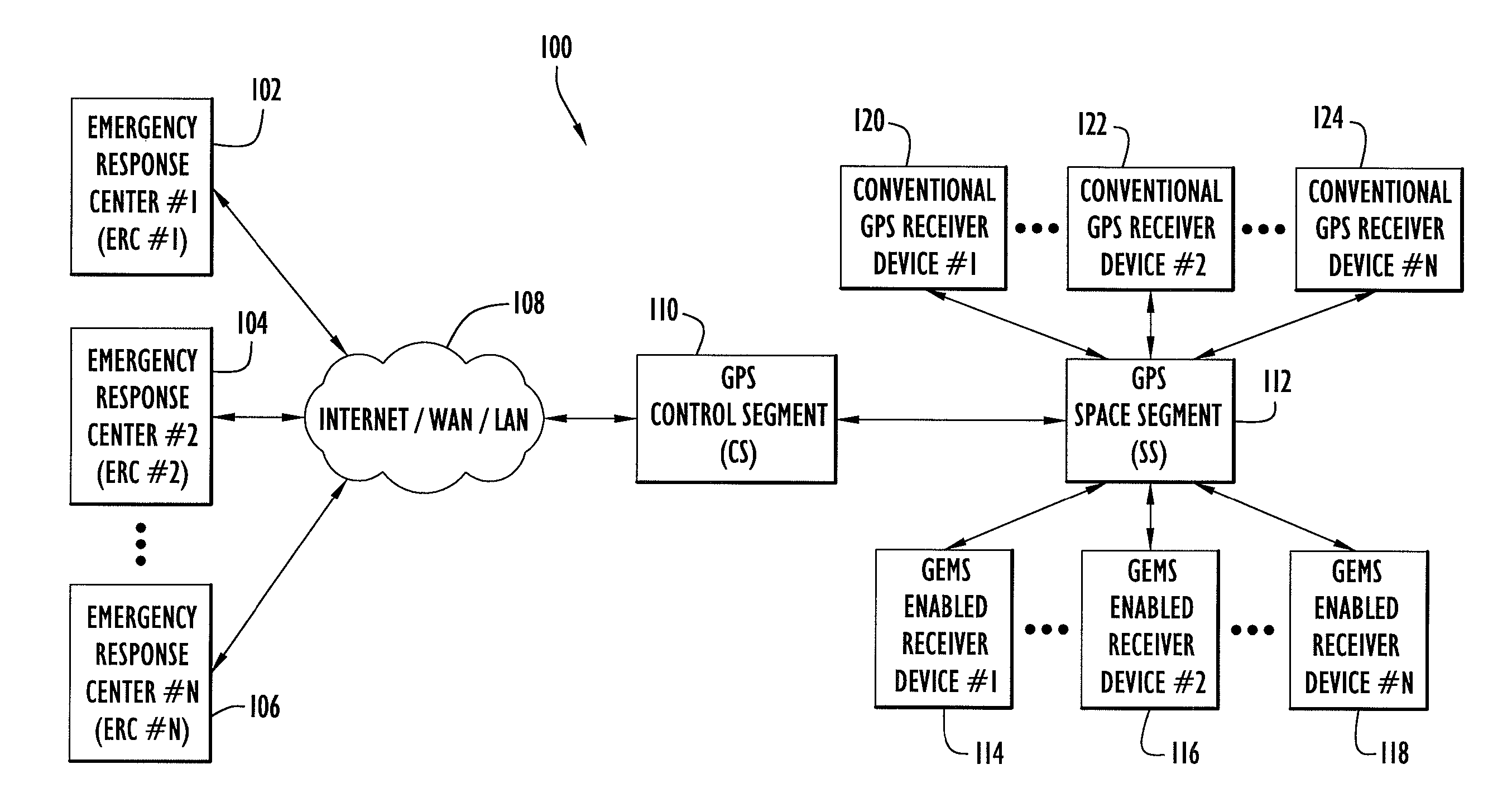
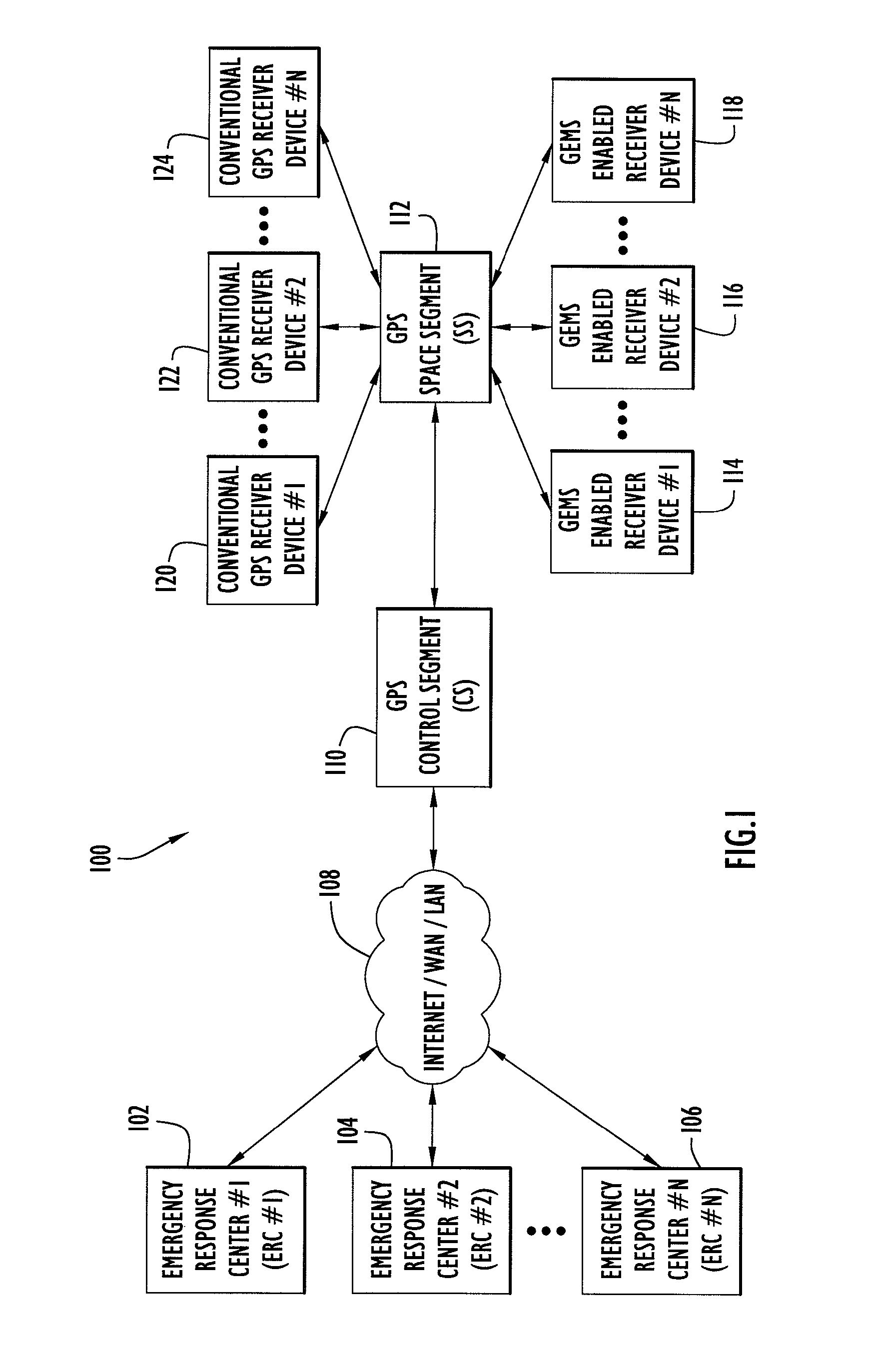
[0038]FIG. 1 is a non-limiting, representative system level diagram of a GPS enabled emergency message system (GEMS) environment in accordance with an exemplary embodiment of the present invention. The GEMS environment includes a plurality of emergency response centers (ERC's) (102, 104 and 106), each with a network connection 108 that can include multiple network components, including private local area network (LAN) segments, private wide area network (WAN) segments, and / or the Internet, by which emergency message requests, with broadcast request times and designated broadcast areas, are transmitted to a GPS ground-based control segment (CS) facility 110. The CS facility processes incomi...


PUM


Abstract

A GPS enabled Emergency Messaging System (GEMS) includes: Emergency Response Centers (ERC's) for defining emergency broadcast messages directed to specified geographic areas; a GPS Control Segment (CS) facility that receives messages generated by the ERC's and coordinates uplink and downlink communications with orbiting GPS satellites; a GPS Space Segment (SS) that includes the multiple orbiting GPS satellites and that receives emergency messages from the CS facility and broadcasts transmissions containing both GPS navigational information and an emergency broadcast message; and GEMS-enabled user equipment that is capable of receiving and processing broadcast emergency messages. The system permits emergency messaging data to be superimposed on the existing GPS signal structure and delivered to users with GPS receivers capable of receiving the superimposed messaging data.

Description

CROSS REFERENCE TO RELATED APPLICATIONS [0001] This application is a continuation of U.S. patent application Ser. No. 10 / 268,096, filed on Oct. 10, 2002, entitled “GPS Enabled Emergency Messaging System,” the entire contents of which are hereby incorporated by reference.BACKGROUND OF THE INVENTION [0002] 1. Field of Invention [0003] The present invention relates to methods and apparatus for implementing a satellite-based emergency broadcast system and, more particularly, to methods and apparatus associated with an emergency broadcast system that is integrated with infrastructure and communications that support a satellite-based global positioning system. [0004] 2. Description of the Related Art [0005] Global Positioning System (GPS) satellite navigation as exemplified by NAVSTAR / GPS, is an accurate, three-dimensional navigation system that has become one of the most important technologies of the era, impacting a myriad of users from aircraft and ships, to farmers and hikers. The GPS...

Claims


Application Information

Patent Timeline
Patent Type & Authority Applications(United States)
IPC IPC(8): G01S1/00G01S19/02
CPCG01S19/02
Inventor SCHNABEL, JON WILLIAM
Owner STINGRAY IP SOLUTIONS LLC
Learn More