Injection blow moulding of plastics articles

a technology of injection blow molding and plastics articles, which is applied in the field of injection blow molding of plastics articles, can solve the problems of affecting the production rate of plastics articles, affecting the production efficiency of plastics articles, and requiring lower outputs. achieve the effect of maximising the production ra

Active Publication Date: 2009-11-03
SIDERIS CONSTANTINOS
View PDF23 Cites 0 Cited by
  • Summary
  • Abstract
  • Description
  • Claims
  • Application Information

AI Technical Summary

Benefits of technology

[0030]Although numerous different shapes of blow-moulded articles may be formed using the mould set, in a particularly preferred arrangement, the blow-moulding cavities are generally elongate, with the longitudinal axes of the blow-moulding cavities extending generally perpendicularly to the mould-separation direction. Orienting the longitudinal axes of the blow-moulding cavities perpendicular to the common mould-separation direction may provide a compact arrangement and reduce the distance by which the mould set parts must separate to allow removal of the blow-moulded article.
[0086]The composite injection-blow mould set described below as well as the associated mechanisms, can be mounted in / on the clamping unit of a standard injection moulding machine, minimising the investment in machinery. Usually the clamping units of such machines are horizontal but standard machines with vertical clamps can also be used. The present invention also extends to a modified injection moulding machine with re-sized clamping unit (with larger clamping plates, accommodating larger mould thicknesses and / or more cavities, and possibly with adjusted clamping force) and / or a re-sized injection unit, to ensure that the relative sizing of these components of an injection moulding machine are preferentially selected for the present method to maximise output and minimise energy consumption. Depending on the mechanisms for stretching, container removal and preform transfer, it may be beneficial to adjust the programming sequence of the injection-moulding machine in order to better optimise the process. All such modifications and adjustments from the standard injection moulding machines are considered minor and are not expected to have much impact on machine cost. Further, the present invention provides for additional stations to be used for more operations to the ready containers, like filling, capping, handle application, labeling etc.

Problems solved by technology

Machines of many cavities have been developed for high production rates with this ‘two-stage process’, which are prohibitively expensive for processors requiring lower outputs.
Also this‘two-stage process’ is not well suited to containers with asymmetrical shapes (e.g. oval) or with wide neck openings (jars).
One-stage machines have several stations (injection, conditioning, stretch-blow, container ejection) and utilise complex and costly mechanisms for transferring the preforms between stations.
The mould sets used in one-stage machines are costly because, amongst other reasons, some mould components like neck formers or injection cores must be duplicated several times, as several sets are needed to carry preforms from station to station.
Furthermore, these costly mould sets are machine specific and cannot be used on other machines.
In view of these factors, one-stage machines require high capital expenditure per unit of production output.
Disadvantages of the one-stage machines include:the need for complex preform transfer mechanisms,the need for separate clamping mechanisms for injection and blow,the duplication of mould components, andthe relatively low production rates.
The complexity of preform transfer mechanisms and the extent of costly duplication of mould parts is related to the number of process stations or product positions present within the machine or the clamping plates.
Conventional attempts to eliminate some of the disadvantages of the one-stage machines, propose the use of a minimum of three such stations or positions, resulting in either complex transfer mechanisms or duplication of mould parts or both.
Additionally such attempts have not succeeded in offering an increase in the output rates of the commercially available one-stage machines.

Method used


Image

  • Injection blow moulding of plastics articles
  • Injection blow moulding of plastics articles
  • Injection blow moulding of plastics articles

Examples


Embodiment Construction

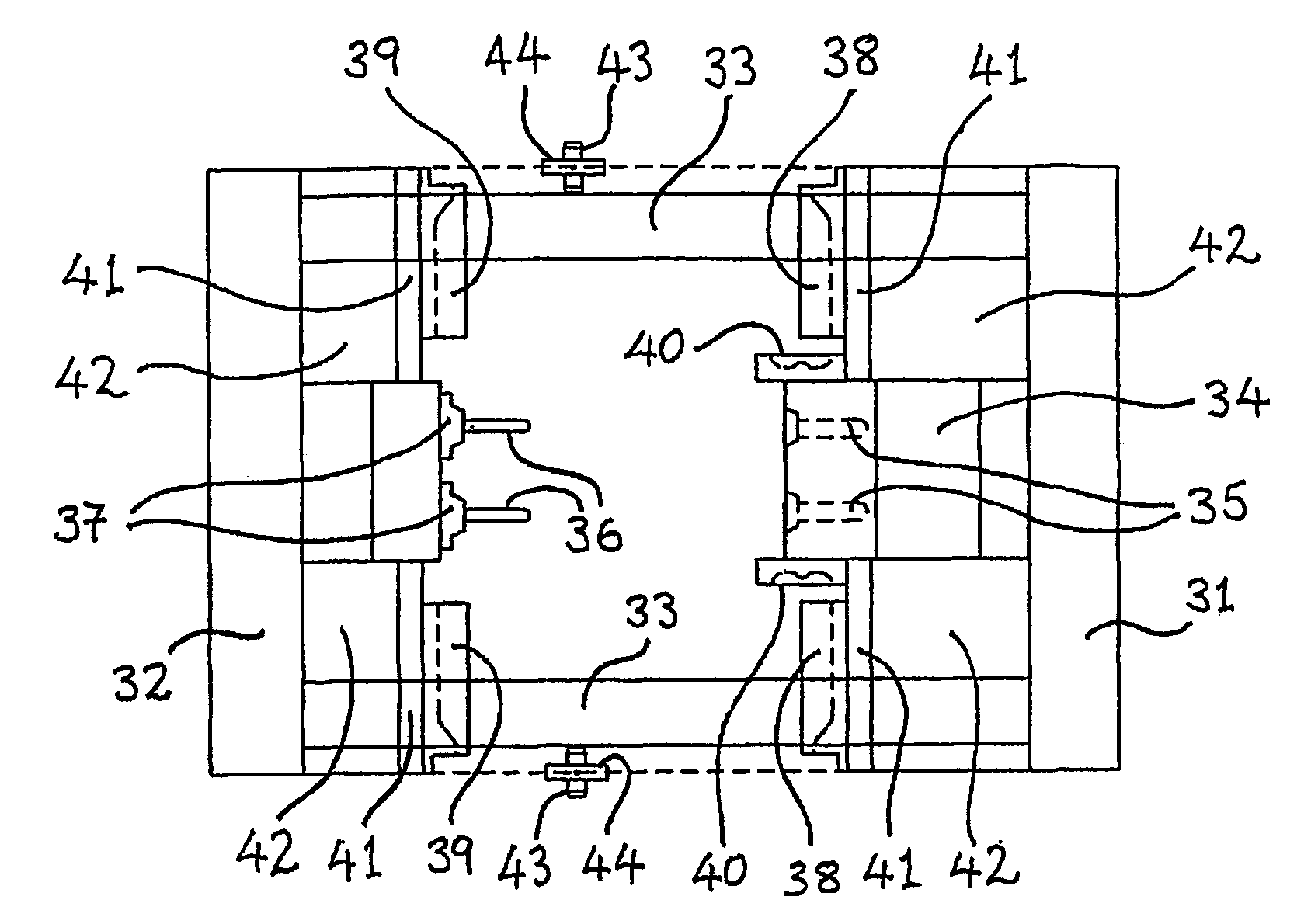
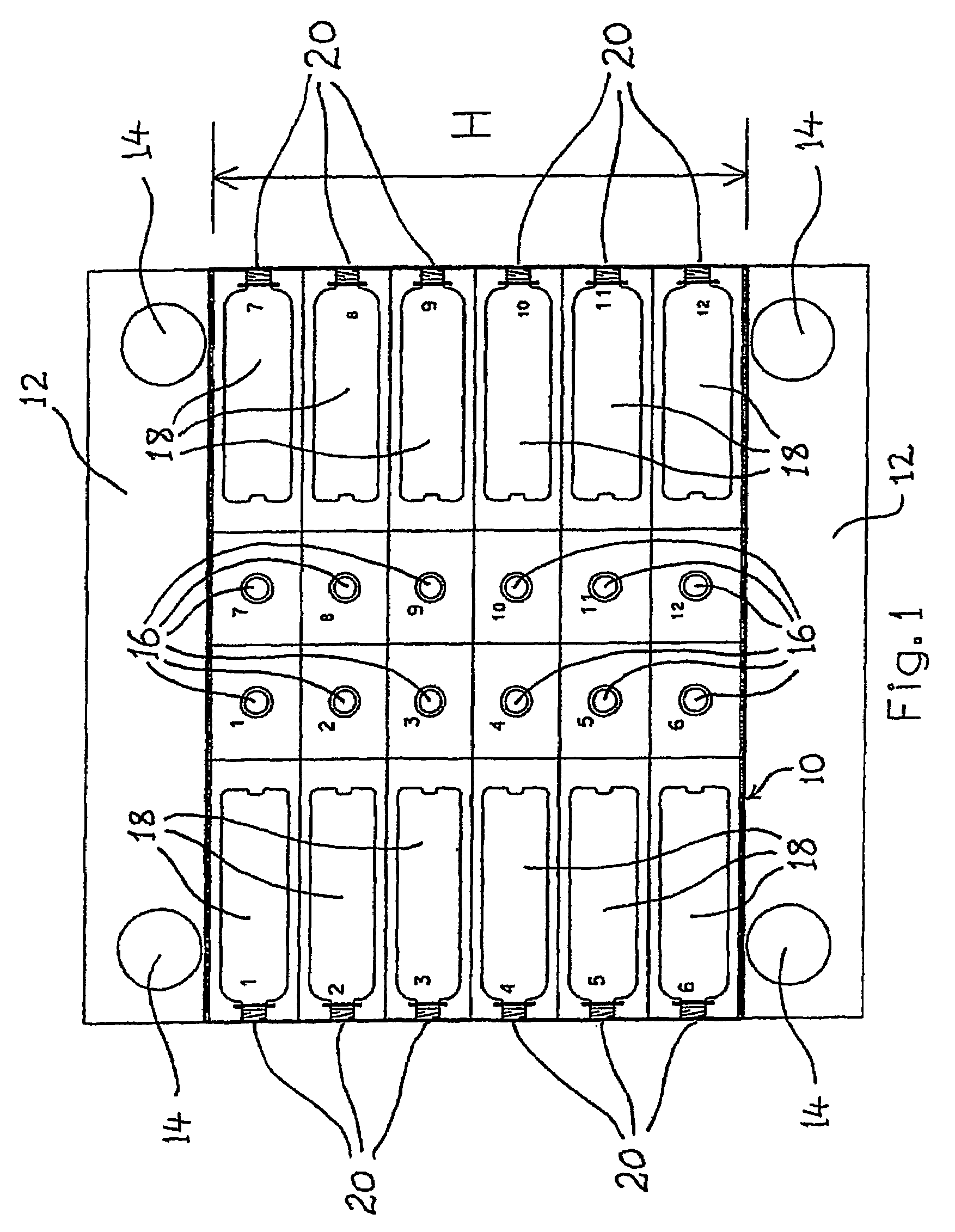
[0113]In the arrangements described below a composite mould set is made up of composite mould halves 10, which are mounted one on each machine clamping plate 12 (or platen) respectively of an injection moulding machine. The clamping plates are connected by four tie bars 14 in conventional manner.

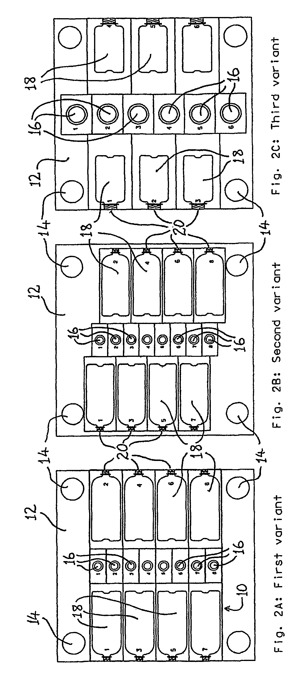
[0114]A variety of different cavity arrangements can be used in the composite mould set of the present invention, with preference being given to symmetrical arrangements for even pressure loading of the clamp unit.

[0115]One such preferred arrangement is illustrated in FIG. 1, in which there are two vertical rows of preform cavities 16 arranged centrally in the machine clamping plate 12. The number of preform cavities per row shown in FIG. 1 is just an example. There could be more or fewer cavities per row, depending on the container's maximum neck diameter, the production output required and the size of the clamping unit of the machine to be used. This cavity arrangement would generally be m...


PUM

PropertyMeasurementUnit
rotationaaaaaaaaaa
rotationaaaaaaaaaa
timeaaaaaaaaaa

Abstract

A composite mould set for use on a conventional type of injection-molding machine is made up of composite mold halves (10) which are mounted one on each platen (12) of the injection molding machine. Each mold half (10) carries an array of injection molding cavities (16) for molding preforms, and an array of blow molding cavities (18) for stretch blow molding of the preforms into a blow molded product. The respective cavities (16) and (18) are arranged so that they open in a common mold separation direction.

Description

[0001]The present invention relates to a method and apparatus for producing plastics articles such as hollow plastics containers (bottles, jars, cups, pails, etc.) by injection stretch blow moulding or injection blow moulding, and in particular but not exclusively to such methods and apparatus using a composite injection-blow mould set and an injection moulding machine.BACKGROUND[0002]Injection and stretch blow moulding machines and mould sets are commercially available for the production of hollow plastic containers. In the ‘two-stage process’, an injection moulding machine is used to mould preforms which are cooled to ambient temperature and stored for later use. Independently a stretch blow moulding machine uses these preforms, reheats them to a stretch-blow temperature, stretches them and blow moulds them in blow mould sets to the shape of the required container. Machines of many cavities have been developed for high production rates with this ‘two-stage process’, which are proh...

Claims


Application Information

Patent Timeline
Patent Type & Authority Patents(United States)
IPC IPC(8): B29C49/06B29C45/26B29C49/12B29C49/42
CPCB29C45/2673B29C49/06B29C49/061B29C49/4205B29C49/48B29C49/12B29L2031/7158B29C2049/4869B29C2049/4871B29K2023/12B29K2025/00B29K2067/00B29K2069/00B29C2045/2679B29C49/4819B29C49/48185B29C49/42087B29C49/42105B29C49/42119B29C2049/023
Inventor SIDERIS, CONSTANTINOS
Owner SIDERIS CONSTANTINOS
Why Eureka
Try Eureka