Thermal head and printing device equipped with the same

a printing device and thermal head technology, applied in printing and other directions, can solve the problems of difficult to achieve further improvement of manufacturing efficiency and complicated manufacturing process, and achieve the effects of improving response, improving thermal efficiency, and reducing the heat storage capacity of the base layer

Inactive Publication Date: 2007-09-20
SONY CORP
View PDF1 Cites 4 Cited by
  • Summary
  • Abstract
  • Description
  • Claims
  • Application Information

AI Technical Summary

Benefits of technology

[0009]Therefore, it is desirable to provide a thermal head capable of achieving improvement of the manufacturing efficiency and a printing device using the same.
[0014]According to the embodiments of the invention, by forming the groove section in the base layer, it becomes difficult to radiate heat from the other surface of the base layer, thus improvement of the thermal efficiency can be achieved, and further, the heat storage capacity of the base layer is reduced, thus improvement of the response can also be achieved. Further, according to the embodiments of the invention, since it is sufficient to adhere the head section provided with the heat generation resistor and the electrodes on the base layer to the heat radiation member, the ceramic substrate in the related art can be eliminated, thus simplification of the configuration can be achieved, and improvement of the production efficiency can also be achieved.

Problems solved by technology

However, although the improvement of the thermal efficiency can be achieved with the thermal head 100 of the above document, it requires an extremely complicated manufacturing process because it is composed of the ceramic substrate 101, the flat glaze layer 102a and the partial glaze layer 102b formed on the ceramic substrate 101, and the heat generation resistor 103 formed on the partial glaze layer 102b, and further the ceramic substrate 101 provided with these components is bonded to the heat radiation member 107 via the adhesion layer 106, thus making it difficult to achieve further improvement of manufacturing efficiency.

Method used


Image

  • Thermal head and printing device equipped with the same
  • Thermal head and printing device equipped with the same
  • Thermal head and printing device equipped with the same

Examples


Embodiment Construction

[0033]Hereinafter, a thermal transfer printing device implementing a thermal head applying an embodiment of the invention will be explained in detail with reference to the accompanying drawings.

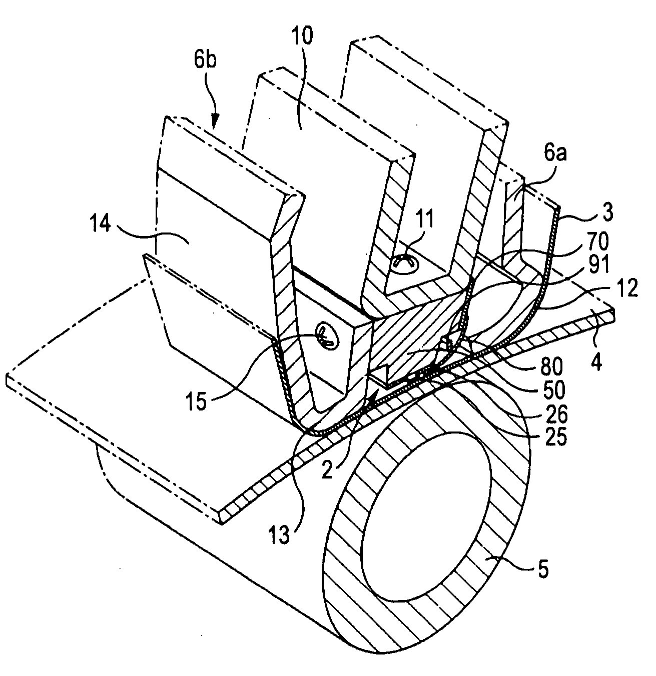
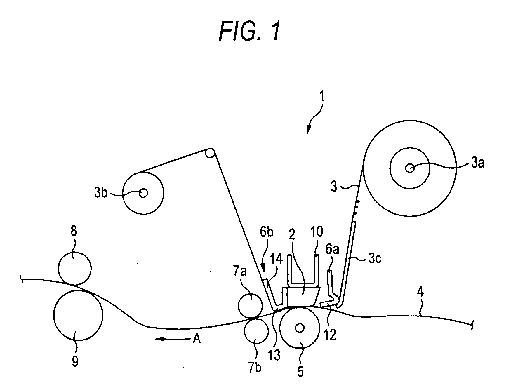
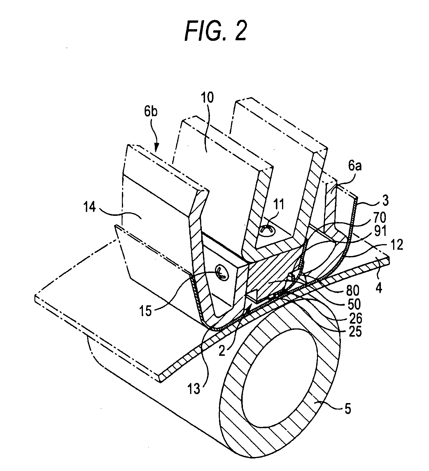
[0034]A thermal transfer printing device 1 (hereinafter referred to as a printing device 1) shown in FIG. 1 is a dye sublimation printer for sublimating a color material of an ink ribbon to thermal-transfer the color material to a print medium, and uses a thermal head 2 applying an embodiment of the invention as a recording head. The printing device 1 applies thermal energy generated by the thermal head 2 to the ink ribbon 3, thereby sublimating the color material of the ink ribbon 3 to thermal-transfer the color material of the ink ribbon 3 to the print medium 4, thus printing color images or characters. The printing device 1 is a home-use printing device, and is able to print on objects of, for example, a post card size as the print medium 4.

[0035]The ink ribbon 3 used here is formed of a l...


PUM


Abstract

A thermal head includes a base layer having a predetermined thickness and provided with a substantially semicylindrical protruding section integrally formed on one surface of the base layer, a heat generation resistor formed on the protruding section, and a pair of electrodes formed on both sides of the heat generation resistor, wherein a part of each of the heat generation resistors exposed between the pair of electrodes is defined as a heat generation section, and the base layer is provided with a groove section formed on the opposite side of the protruding section and having opening on the other surface of the base layer.

Description

CROSS REFERENCES TO RELATED APPLICATIONS[0001]The present invention contains subject matter related to Japanese Patent Application JP 2006-075639 filed in the Japan Patent Office on Mar. 17, 2006, the entire contents of which being incorporated herein by reference.BACKGROUND OF THE INVENTION[0002]1. Technical Field[0003]The present invention relates to a thermal head for thermal-transferring a color material on an ink ribbon to a print medium and a printing device.[0004]2. Related Art[0005]As a printing device for printing images or characters on a print medium, there is a thermal transfer printing device (hereinafter simply referred to as a printing device) which sublimates a color material forming an ink layer provided to one surface of an ink ribbon to thermal-transfer the color material to a print medium, thereby printing color images or characters. The printing device is provided with a thermal head for thermal-transferring the color material on the ink ribbon to the print medi...

Claims


Application Information

Patent Timeline
Patent Type & Authority Applications(United States)
IPC IPC(8): B41J2/05
CPCB41J2/33585B41J2/32B41J2/335B41J2/345
Inventor KOYAMA, NOBORUKARIYA, IZUMIYANASE, MITSUOMORIKAWA, TORU
Owner SONY CORP
Why Eureka
Try Eureka