In-plane switching liquid crystal display apparatus

a liquid crystal display and switching liquid crystal technology, applied in non-linear optics, instruments, optics, etc., can solve the problems of low throughput, high cost, and insufficient white luminance to achieve sufficient contrast, etc., to achieve high contrast, facilitate alignment, and high picture quality

Active Publication Date: 2007-09-20
NEC LCD TECH CORP
View PDF5 Cites 33 Cited by
  • Summary
  • Abstract
  • Description
  • Claims
  • Application Information

AI Technical Summary

Benefits of technology

[0031] In accordance with the present invention, the pretwist angle of the liquid crystal molecules is set to 0 degrees in the pixel region between the pixel electrode and the common electrode; and the shapes of the pixel electrode and the common electrode are established so as to form a principal portion whose electric field direction is orthogonal to the initial alignment direction of the liquid crystal molecules, and a specific portion that is smaller than the principal portion and whose electric field is not orthogonal, whereby the alignment of the liquid crystal molecules in the specific portion is uniformly changed by the electric field, and the alignment of the liquid crystal molecules in the principal portion also changes in conformity with the uniform change. Since the initial alignment direction of the liquid crystal molecules in the principal portion is parallel to the common electrode and the pixel electrode, aligning is facilitated. In cases in which the rubbing technique is used for initial alignment, the rubbing direction and the direction of extension of the electrodes are for the most part parallel, making it possible to avoid the problem of deviation in alignment direction in proximity to areas of level difference produced by the electrode film. Moreover, since the specific portion occupies only a small proportion of the pixel region, there is substantially no effect of light leakage in the black state. Accordingly, it is possible to achieve a liquid crystal display apparatus having high contrast and high picture quality.

Problems solved by technology

As a result, the liquid crystal molecules are able to rotate either left or right, and disclination lines of discontinuous alignment of the liquid crystal molecules occur at the boundaries of domains of mutually opposing rotation directions, causing picture quality to deteriorate.
However, if the pretwist angle is too large, the white luminance will not be high enough for sufficient contrast to be achieved.
However, special techniques such as segmented rubbing or photo-alignment are required, and throughput is low while costs are high.
However, the prior art discussed above has a number of problems such as the following.
In cases in which the comb-shaped electrodes are formed from a metal film, a difference in level produced by the metal film will become a problem.
In the case of the rubbing technique, which represents the most common aligning means, deviation of the alignment direction occurs in proximity to areas of level difference, causing light leakage in the black state.
A resultant problem is that contrast is lower.
Accordingly, with the rubbing technique there is the problem of a possible increase in light leakage, and further disadvantages in terms of contrast.
However, the initial alignment direction is inclined with respect to the direction of extension of the parallel electrode portion, creating the problem of lower contrast with the rubbing technique, similar to that discussed above.
However, requirements for high contrast have become very stringent in recent years, to the point that the slight leakage of light produced by a small level difference can no longer be ignored.

Method used


Image

  • In-plane switching liquid crystal display apparatus
  • In-plane switching liquid crystal display apparatus
  • In-plane switching liquid crystal display apparatus

Examples


first embodiment

[0045] The embodiments of the present invention will be described in detail hereinbelow with reference to the accompanying drawings. First, the liquid crystal display apparatus in accordance with the present invention will be described. FIG. 6 is a schematic plan view showing a pixel of the liquid crystal display apparatus in accordance with the present embodiment. The plan views illustrating the embodiments herein are schematic diagrams representing the display region only.

[0046] The liquid crystal display apparatus in accordance with the embodiments of the present invention is an in-plane switching liquid crystal display apparatus that operates on an active matrix principle and has a liquid crystal layer sandwiched between a pair of opposing substrates, a display region composed of multiple pixels formed on the substrate surfaces, and a pixel electrode and common electrode formed in each pixel region on the surface of one of the substrates. An electric field substantially parallel...

second embodiment

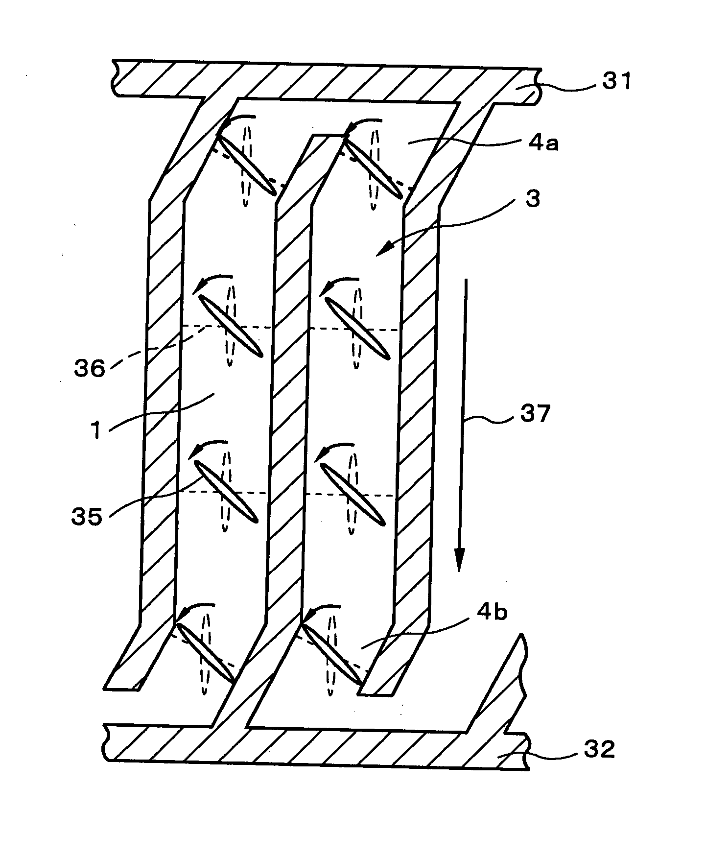
[0054] Next, the liquid crystal display apparatus according to the present invention will be described. FIG. 8 is a schematic plan view showing a pixel of the liquid crystal display apparatus in accordance with the present embodiment. As shown in FIG. 8, a comb-shaped common electrode 31 and pixel electrode 32 are disposed mutually parallel in an interlocking fashion in a pixel to form columns 3 enclosed by the common electrode 31 and the pixel electrode 32. The initial alignment direction 37 of the liquid crystal molecules is constant throughout the. columns 3.

[0055] The pixel region between the common electrode 31 and the pixel electrode 32 in the present embodiment is composed of a principal portion 1 in which the direction of extension of the common electrode 31 and the pixel electrode 32 is parallel with the liquid crystal molecule initial alignment direction 37, and specific portions 4a, 4b not parallel with the liquid crystal molecule initial alignment direction 37. The speci...

third embodiment

[0060] Next, the present invention will be described. FIG. 10 is a schematic plan view showing a pixel of the liquid crystal display apparatus in accordance with the present embodiment. As shown in FIG. 10, a comb-shaped common electrode 51 and pixel electrode 52 are disposed mutually parallel in an interlocking fashion in a pixel to form columns 3 enclosed by the common electrode 51 and the pixel electrode 52. The initial alignment direction 57 of the liquid crystal molecules is constant throughout the columns 3.

[0061] The pixel region between the common electrode 51 and the pixel electrode 52 in the present embodiment is composed of a principal portion 1 in which the direction of extension of the common electrode 51 and the pixel electrode 52 is parallel with the liquid crystal molecule initial alignment direction 57, and a specific portion 5 not parallel with the liquid crystal molecule initial alignment direction 57. The specific portion 5 is provided in the medial portion of th...


PUM

PropertyMeasurementUnit
pretwist angleaaaaaaaaaa
angleaaaaaaaaaa
pre-tilt angleaaaaaaaaaa

Abstract

A pixel region between a common electrode and a pixel electrode is composed of a principal portion in which the direction of extension of the common electrode and the pixel electrode is parallel with the initial alignment direction of the liquid crystal molecules, and a specific portion not parallel with the initial alignment direction of the liquid crystal molecules. In the specific portion, the distal portion of the pixel electrode and the basal portion of the common electrode are mutually parallel and inclined by a prescribed angle with respect to the initial alignment direction of the liquid crystal molecules. When voltage is applied across the common electrode and the pixel electrode to generate a horizontal electric field, the horizontal electric field will be perpendicular to the initial alignment direction of the liquid crystal molecules within the principal portion that occupies a major part of a column, whereas the field will not be perpendicular within the specific portion. The principal portion occupies the major part of the column.

Description

BACKGROUND OF THE INVENTION [0001] 1. Field of the Invention [0002] The present invention relates to an in-plane switching liquid crystal display apparatus, and relates in particular to an in-plane switching liquid crystal display apparatus operating on an active matrix principle. [0003] 2. Description of the Related Art [0004] The in-plane switching (IPS) format has come to enjoy widespread use in big screen monitors such as TVs. In the IPS format, display takes place through rotation of the liquid crystals about the molecular axes within a plane parallel to the substrate under the action of a horizontal electric field generated parallel to the substrate. With this format, the viewing angle is not dependent on the rise angle of the molecular axes, and viewing angle characteristics are therefore markedly improved over those of twisted nematic (TN) format. [0005] While the IPS format offers advantages in terms of viewing angle characteristics, a pretwist angle must be provided in ord...

Claims


Application Information

Patent Timeline
Patent Type & Authority Applications(United States)
IPC IPC(8): G02F1/1343
CPCG02F2201/124G02F1/134363
Inventor KONNO, TAKAYUKI
Owner NEC LCD TECH CORP
Why Eureka
Try Eureka