
Support Device for Positioning an Optical Element

a technology of supporting elements and supporting elements, which is applied in the direction of microlithography exposure apparatuses, printers, instruments, etc., can solve the problems of increasing the mass of the optical elements to be moved during adjustment, increasing the stress within the supporting elements supporting the respective optical elements, and increasing the number of numerical apertures of the optical system. , to achieve the effect of reducing design, construction and control effort, high degree of imaging accuracy, and high accuracy

Inactive Publication Date: 2007-09-20
CARL ZEISS SMT GMBH
View PDF10 Cites 21 Cited by
  • Summary
  • Abstract
  • Description
  • Claims
  • Application Information

AI Technical Summary

Benefits of technology

[0007] In the general context of the above parallel kinematics, US 2002 / 0020069 A1 to Bottinelli et al. discloses a support device for positioning a body in space. In one embodiment this support device comprises three support units supporting said body. Each of said support units is mounted movably to a guide rail on a supporting structure for positioning the body by translating the respective support unit along its guide rail. Due to the kinematically serial arrangement of the drive mechanism within the kinematic chain of the positioning structure such a guide rail solution is not desirable for supporting an optical element to be used in the context of the above micro-lithography processes. This is due to the fact that such a solution is prone to not provide the necessary accuracy over the time due to effects of wear or setting. Otherwise, such a solution would require undesired additional effort for avoiding the above disadvantageous effects.
[0008] Furthermore, also in the general context of the above parallel kinematics, U.S. Pat. No. 4,976,582 to Clavel discloses a support device for positioning a movable element, such as a tool, in space using rod kinematics as support units. In one embodiment each of said support units is mounted movably to a longitudinal guide mechanism on a supporting structure for positioning the body by translating the respective support. This solution is similar to the above solution disclosed by Bottinelli et al. (US 200210020069 A1) and suffers form the same disadvantages. In another embodiment each of said support units is mounted movably to a rotational guide mechanism on a supporting structure for positioning the body by rotating parts of the respective support unit. Such a rotational guide solution, as well, is not desirable for supporting an optical element to be used in the context of the above micro-lithography processes. This is due to the fact that, again due to the kinematically serial arrangement of the drive mechanism within the kinematic chain of the positioning structure, such a solution is also prone to not providing the necessary accuracy over the time due to effects of wear or setting. Otherwise, such a solution as well would require undesired additional effort for avoiding the above disadvantageous effects. Furthermore, the rod kinematics themselves comprise several such rotational guides. Thus, for the reason outlined above, they are not desirable for supporting an optical element to be used in the context of the above micro-lithography processes. SUMMARY OF THE INVENTION
[0009] It is thus an object of the present invention to provide for positioning of an optical element, in particular a lens, in space in three translatory directions arranged mutually transverse to each other that, at least to some extent, overcomes the above disadvantages.
[0010] It is a further object of the present invention to provide for positioning of an optical element, in particular a lens, in space in three translatory directions arranged mutually transverse to each other allowing for a high degree of imaging accuracy with a corresponding optical system.
[0011] It is a further object of the present invention to provide for positioning of an optical element, in particular a lens, in space in three translatory directions arranged mutually transverse to each other at a reduced design, construction and control effort.
[0012] It is a further object of the present invention to provide for positioning of an optical element, in particular a lens, in space in three translatory directions arranged mutually transverse to each other at high accuracy and with good repeatability over time.

Problems solved by technology

A further problem in this context lies within the increased dimensions and, thus, the increased mass of the optical elements due to the increased numerical aperture of the optical system.
On the one hand, the increased mass of the optical elements to be moved during adjustment poses dynamic problems due to the lowered resonant frequencies of the system.
Furthermore, the increased mass of the optical elements to be supported leads to increased stresses within the support elements supporting the respective optical element.
This serial arrangement, on the one hand, leads to an accumulation of the positioning errors and, thus, either more or less poor adjustment quality or increased effort to obtain satisfactory positioning accuracy.
Furthermore, due to the actuators to be moved, such a serial arrangement implies a considerable mass to be moved and, thus, undesired low resonant frequencies of the support and lens system.
Anyway, it shows the disadvantage of a very complicated design with a large number of movable parts and manipulating mechanisms for moving those movable parts.
Furthermore, the large number of manipulating mechanisms leads to an increased effort for controlling the manipulation and, thus, the positioning process.
Due to the kinematically serial arrangement of the drive mechanism within the kinematic chain of the positioning structure such a guide rail solution is not desirable for supporting an optical element to be used in the context of the above micro-lithography processes.
This is due to the fact that such a solution is prone to not provide the necessary accuracy over the time due to effects of wear or setting.
Otherwise, such a solution would require undesired additional effort for avoiding the above disadvantageous effects.
Such a rotational guide solution, as well, is not desirable for supporting an optical element to be used in the context of the above micro-lithography processes.
This is due to the fact that, again due to the kinematically serial arrangement of the drive mechanism within the kinematic chain of the positioning structure, such a solution is also prone to not providing the necessary accuracy over the time due to effects of wear or setting.
Otherwise, such a solution as well would require undesired additional effort for avoiding the above disadvantageous effects.
Thus, for the reason outlined above, they are not desirable for supporting an optical element to be used in the context of the above micro-lithography processes.

Method used


Image

  • Support Device for Positioning an Optical Element
  • Support Device for Positioning an Optical Element
  • Support Device for Positioning an Optical Element

Examples


Embodiment Construction

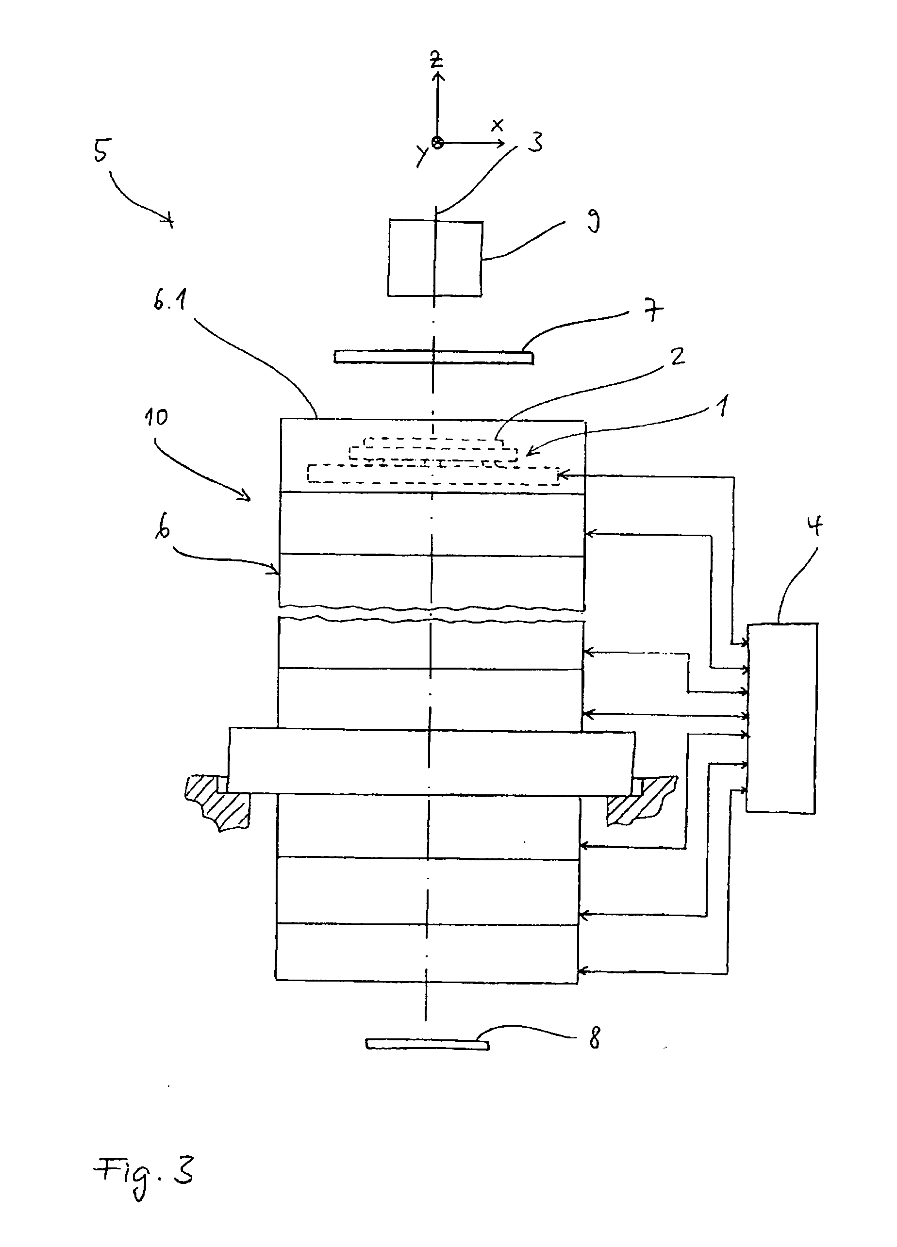
[0029] In the following, a first preferred embodiment of a support device according to the present invention and a preferred embodiment of an optical exposure apparatus according to the present invention comprising a preferred embodiment of a lens barrel according to the present invention will be described with reference to FIGS. 1 to 3.

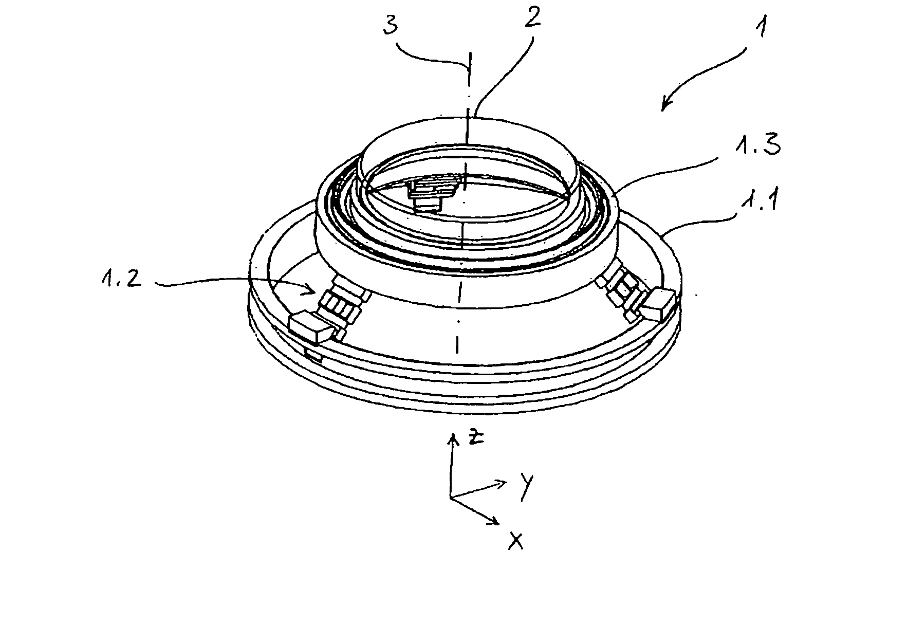
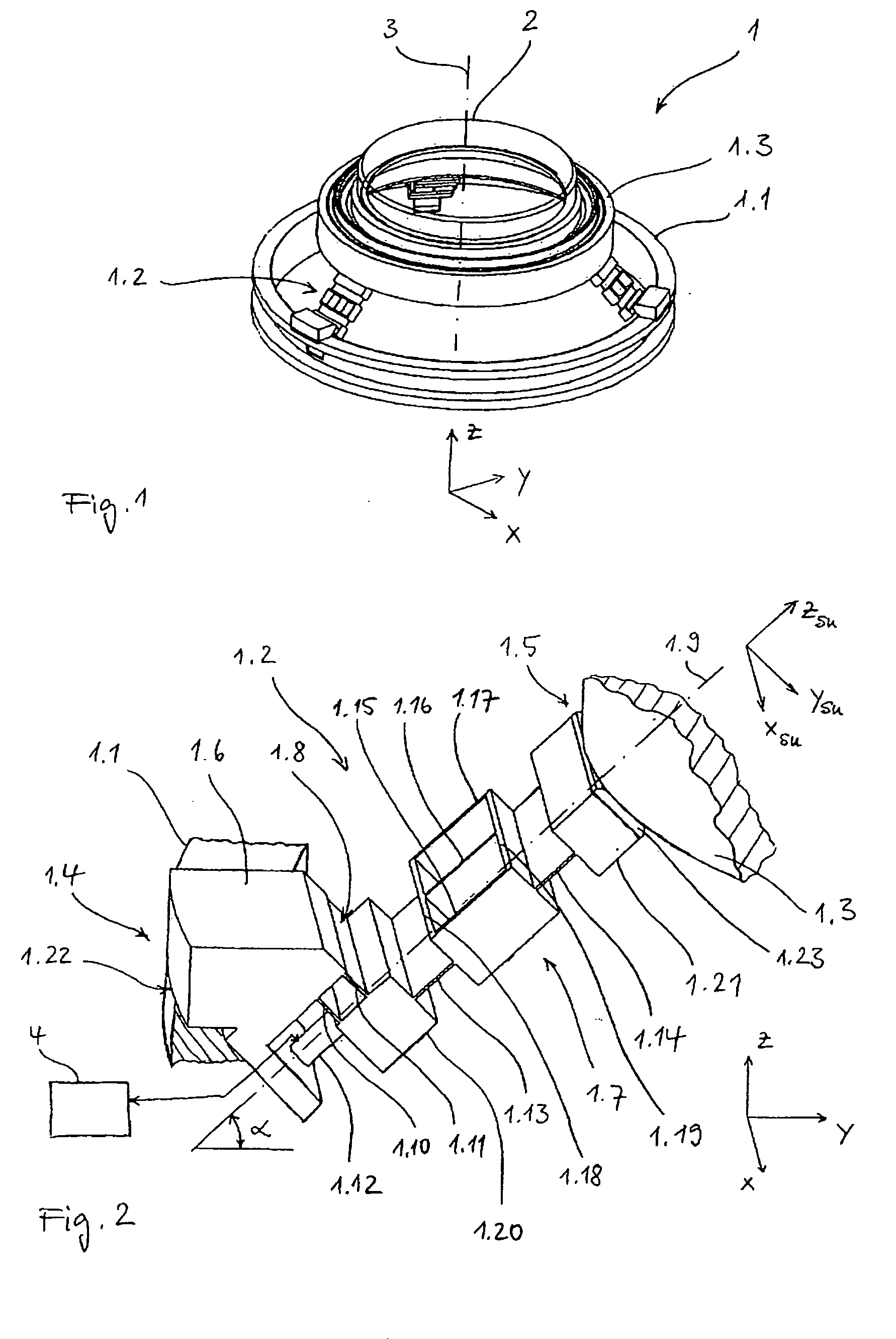
[0030]FIG. 1 is a schematic perspective view of a support device 1 for positioning an optical element in the form of a lens 2. Anyway, it will be appreciated that, with other embodiments of the present invention, any other type of optical elements may be positioned. The support device 1 comprises a first frame unit 1.1 and three identical support units 1.2 distributed equiangularly at the circumference of the first frame unit 1.1 for supporting a second frame unit 1.3 carrying the lens 2.

[0031] As will be explained in detail further below, the support units 1.2 together are arranged for positioning the lens 2 along a translatory first direction X, ...


PUM


Abstract

Support device for positioning an optical element (2), in particular a lens, comprising a first frame unit (1.1) and a plurality of support units (1.2) for supporting said optical element (2), each of said support units (2) having a first end for fixedly engaging a part of said first frame unit (1.1) and a second end for supporting said optical element (2), said support units (1.2) being arranged for positioning said optical element (2) along a first direction, a second direction and a third direction in the manner of parallel kinematics, said first direction, said second direction and said third direction being translatory directions arranged mutually transverse to each other, wherein there are provided three support units (1.2) and wherein each of said support units (1.2) provides for restriction of a first degree of freedom and a second degree of freedom to support said optical element (2) in an isostatic manner.

Description

BACKGROUND OF THE INVENTION [0001] The present invention relates to a support device for positioning an optical element, in particular for positioning a lens. Furthermore, it relates to a lens barrel comprising such a support device and an optical exposure apparatus comprising such a lens barrel. The invention may be used in the context of photolithography processes for fabricating microelectronic devices, in particular semiconductor devices, or in the context of fabricating devices, such as masks or reticles, used during such photolithography processes. [0002] Typically, the optical systems used in the context of fabricating microelectronic devices such as semiconductor devices comprise a plurality of optical elements such as lenses. Those lenses usually cooperate in an exposure process to transfer an image formed on a reticle or the like onto a substrate such as a wafer. Due to the ongoing miniaturization of semiconductor devices there is a permanent need for enhanced resolution o...

Claims


Application Information

Patent Timeline
IPC IPC(8): G03F7/20G02B7/02G02B7/182
CPCG03F7/70825G02B7/023
Inventor KUGLER, JENSWEBER, ULRICHHAFENRICHTER, SABINE
Owner CARL ZEISS SMT GMBH
Learn More