Anti-reflection microstructure, anti-reflection mold body, and method of manufacturing the same

a mold body and anti-reflection technology, applied in the field of anti-reflection microstructure and anti-reflection mold body, can solve the problem that the anti-reflection mold body fails to achieve a sufficient anti-reflection effect, and achieve the effect of superior anti-reflection function

Inactive Publication Date: 2007-09-20
NISSAN MOTOR CO LTD
View PDF4 Cites 11 Cited by
  • Summary
  • Abstract
  • Description
  • Claims
  • Application Information

AI Technical Summary

Benefits of technology

[0012] An object of the present invention is to provide an anti-reflection microstructure having a superior anti-reflection function, an anti-reflection mold body including the microstructure, a manufacturing method thereof, and more specifically to provide an automobile component such as a meter front cover or a windshield which includes the anti-reflection microstructure.

Problems solved by technology

As a consequence, this anti-reflection mold body fails in achieving a sufficient anti-reflection effect.

Method used


Image

  • Anti-reflection microstructure, anti-reflection mold body, and method of manufacturing the same
  • Anti-reflection microstructure, anti-reflection mold body, and method of manufacturing the same
  • Anti-reflection microstructure, anti-reflection mold body, and method of manufacturing the same

Examples


example 1

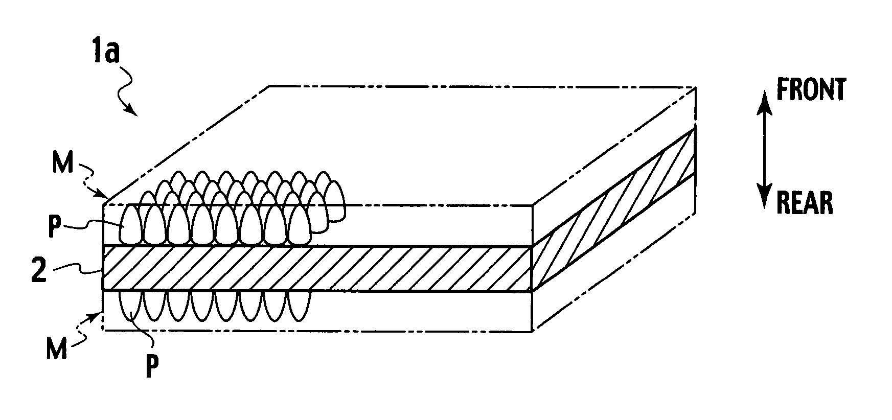
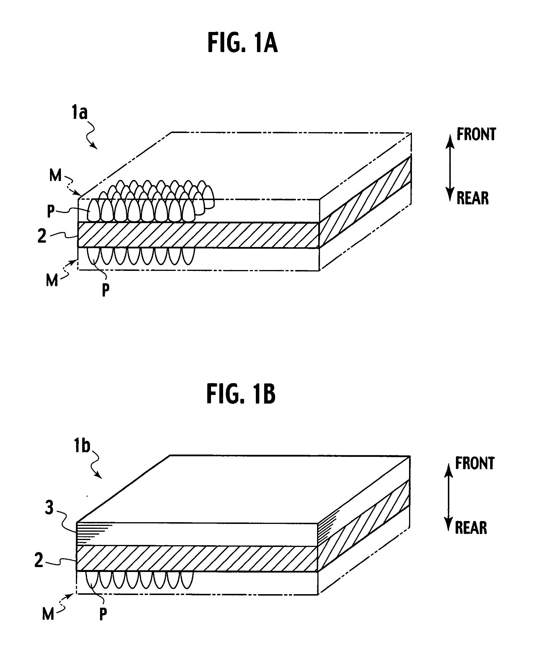
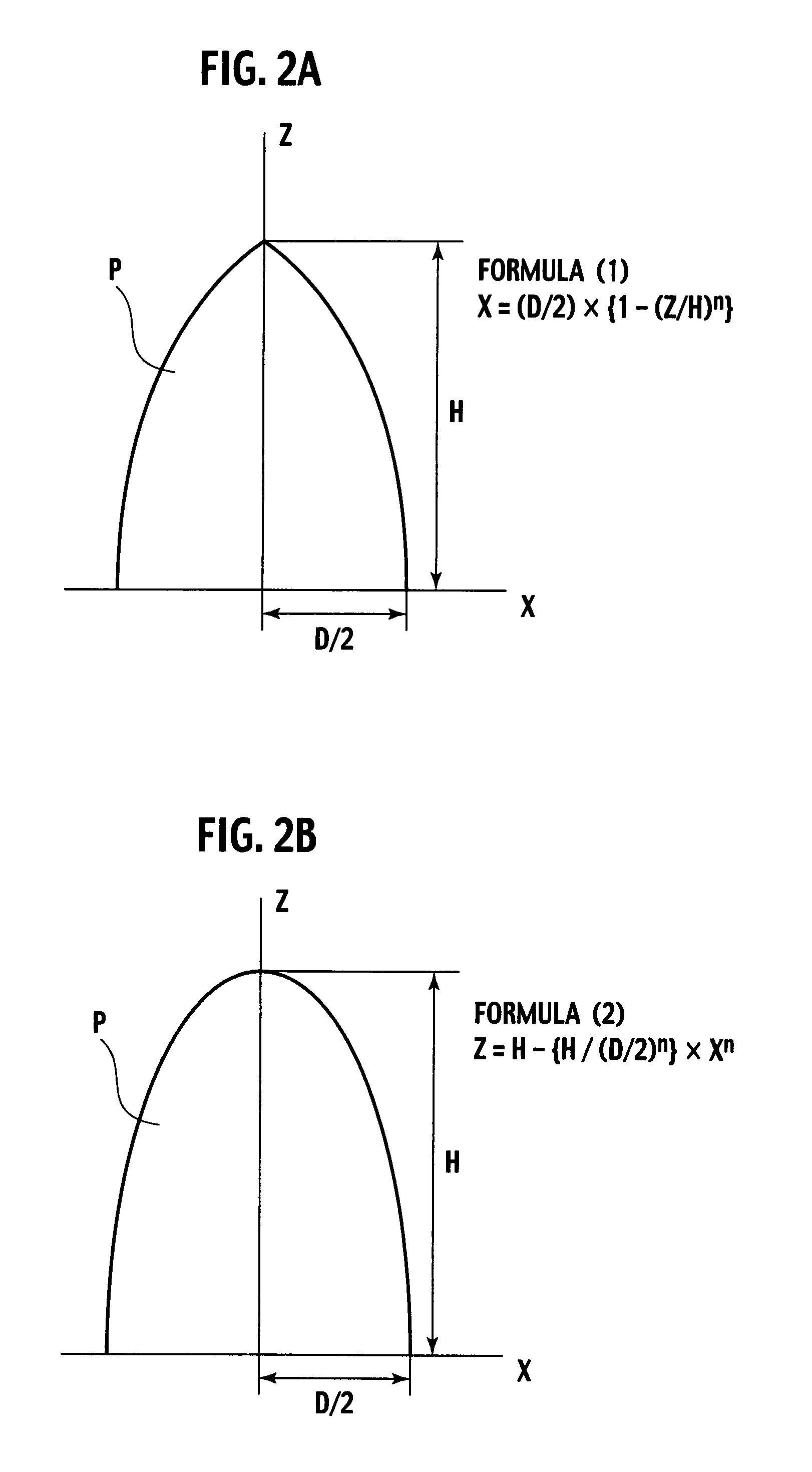
[0051] A die was fabricated by use of a commercially available electron beam lithography system. This die was heated up to 150° C., and then pressed against both surfaces of a polymethylmethacrylate base material at a pressure of 10 MPa for 1 hour. Thereafter, the base material was cooled down to 70° C. or below. In this way, an anti-reflection mold body was fabricated, provided with anti-reflection microstructures M where the fine convex portions P are arranged in a hexagonal close-packed structure. The convex portion P had a square base, a diameter D of a circumscribed circle thereof equal to 250 nm, and a height H equal to 500 nm (H / D=2). An edge line shape thereof was expressed by the 1.2th order linear formula (1).

[0052] The anti-reflection mold body thus obtained was subjected to measurement of average reflection rate at a light incident angle of 0 degrees and in a wavelength range from 380 to 780 nm by use of a multi-angle spectrophotometer (made by Otsuka Electronics, Co., ...

example 2

[0053] By repeating the same operations as Example 1, another die was fabricated by use of the same electron beam lithography system. Using the die, an anti-reflection mold body was fabricated, provided with anti-reflection microstructures M in which the fine convex portions P are arranged in a hexagonal close-packed structure, on both surfaces of the polymethylmethacrylate base material. The convex portion P had a square base, a diameter D of a circumscribed circle thereof equal to 250 nm, and a height H equal to 750 nm (H / D=3). An edge line shape thereof was expressed by the 1.5th order linear formula (1).

[0054] The anti-reflection mold body thus obtained was subjected to measurement of average reflection rate at the light incident angle of 0 degrees and in the wavelength range from 380 nm to 780 nm by use of the same multi-angle spectrophotometer. The average reflection rate was equal to 0.06%.

example 3

[0055] By repeating the same operations as Example 1, another die was fabricated by use of the same electron beam lithography system. Using the die, an anti-reflection mold body was fabricated, provided with anti-reflection microstructures M where the fine convex portions P are arranged in a hexagonal close-packed structure on both surfaces of the polymethylmethacrylate base material. The convex portion P had a square base, a diameter D of a circumscribed circle thereof equal to 300 nm, and a height H equal to 300 nm (H / D=1). An edge line shape thereof was expressed by the second order linear formula (1).

[0056] The anti-reflection mold body thus obtained was subjected to measurement of average reflection rate at the light incident angle of 0 degrees and in the wavelength range from 380 nm to 780 nm by use of the same multi-angle spectrophotometer. The average reflection rate was equal to 0.51%.


PUM

PropertyMeasurementUnit
diameteraaaaaaaaaa
transparentaaaaaaaaaa
wavelengthaaaaaaaaaa

Abstract

An anti-reflection microstructure including: convex portions arranged at a pitch shorter than a wavelength of visible light, each of the convex portions having a conic shape defined by an apex, a lateral surface, and a base, wherein an intersecting line between the lateral surface and a plane which passes through the apex and is perpendicular to the base, is equivalent to a curve expressed by an nth-order linear formula in which 1<n≦3.

Description

BACKGROUND OF THE INVENTION [0001] 1. Field of the Invention [0002] The present invention relates to an anti-reflection microstructure having a function for preventing light reflection, to an anti-reflection mold body which includes the anti-reflection microstructure and is suitable for applications as a non-reflective panel for various meters, display devices, etc. to be installed in a vehicle such as an automobile, a ship, or an airplane, and further to a method of manufacturing the anti-reflection mold body. [0003] 2. Description of the Related Art [0004] When outside light or room illumination is projected on a screen of a display device such as a liquid crystal display or a CRT display, for example, on a household television screen, visibility of screen images is substantially deteriorated. [0005] In an automobile, a display unit accommodating a variety of indicators such as a speedometer or a fuel gauge is provided in front of a driver's seat. The display unit has a meter fron...

Claims


Application Information

Patent Timeline
Patent Type & Authority Applications(United States)
IPC IPC(8): F21V9/04B29C59/02B29L11/00G02B1/11G02B1/118
CPCG02B1/118G02B1/11G02F2201/38
Inventor NOGUCHI, YUJIFUKUI, TAKAYUKI
Owner NISSAN MOTOR CO LTD
Why Eureka
Try Eureka