Overvoltage protection device with simplified display system and corresponding production method

a technology of display system and overvoltage protection device, which is applied in the direction of circuit-breaking switch, circuit-breaking switch for excess current, emergency protective arrangement for limiting excess voltage/current, etc., can solve the problem that the protection component cannot conduct default current, and the installation is damaged gravely, etc. problem, to achieve the effect of protecting the electrical installation

Active Publication Date: 2007-09-20
ABB FRANCE SAS
View PDF2 Cites 17 Cited by
  • Summary
  • Abstract
  • Description
  • Claims
  • Application Information

AI Technical Summary

Benefits of technology

[0019] The features of the present invention address the various disadvantages mentioned above and provide a device for protecting an electrical installation from overvoltages, in which the design of the signalling means is particularly simple and reliable.
[0020] A feature of the present invention is to provide an overvoltage protection device having a safety mechanism that, in the event of failure of the protection component, is particularly reliable.
[0021] Another feature of the present invention is to provide an overvoltage protection device that is particularly simple and inexpensive to produce.
[0022] Another feature of the present invention is to provide a method for producing an overvoltage protection device that is particularly simple and inexpensive.

Problems solved by technology

In the event of a failure, in particular, at the end of their lifetime, protection components may be subject to significant heating that can cause serious damage to the installation and present risks to the user, for example, by starting a fire.
When the thermal disconnection means are activated, the thermal disconnection means isolate the protection component from the electrical installation to be protected, so that the protection component is incapable of conducting default currents and no longer performs the function of protecting the electrical installation.
Thus, when the protection component is disconnected, the free end of the spring leaf can interfere with the slider to exert a stress on the slider and propel the slider in translation along a trajectory substantially tangential to the spring leaf.
While these devices are generally satisfactory, the devices of the prior art can have notable disadvantages.
Such parts are, by nature, difficult to produce and to assemble, which tends to increase the costs of production of devices equipped with them.
In addition, the devices of the prior art sometimes have reliability problems with regard to the disconnection, due to the resistance on the signalling slider opposing the opening of the disconnection means.
Indeed, the slider is subjected to frictional forces that resist the movement of the slider, and the slider can even be jammed by seizing or sticking at the level of the casing, which has the effect of impeding, slowing or even prematurely blocking the movement of the disconnection leaf.
Thus, in the case of a severe failure of the signalling means, the signalling means are capable of preventing the effective disconnection of a defective component, consequently, leading to dangerous heating or even short-circuiting of the installation.
The small area of the connection puts the connection at risk for an unexpected dislocation, in particular, when the device is subjected to vibrations or shocks, and such a dislocation would lead to a rupture in the connection and random or erroneous signalling that does not reflect the real state of the device.
In addition, the fineness of such a connection makes the connection particularly sensitive to dimensional variations in the production of the constituent elements, making it necessary to maintain restrictive provisions during production and / or assembly.

Method used


Image

  • Overvoltage protection device with simplified display system and corresponding production method
  • Overvoltage protection device with simplified display system and corresponding production method
  • Overvoltage protection device with simplified display system and corresponding production method

Examples


Embodiment Construction

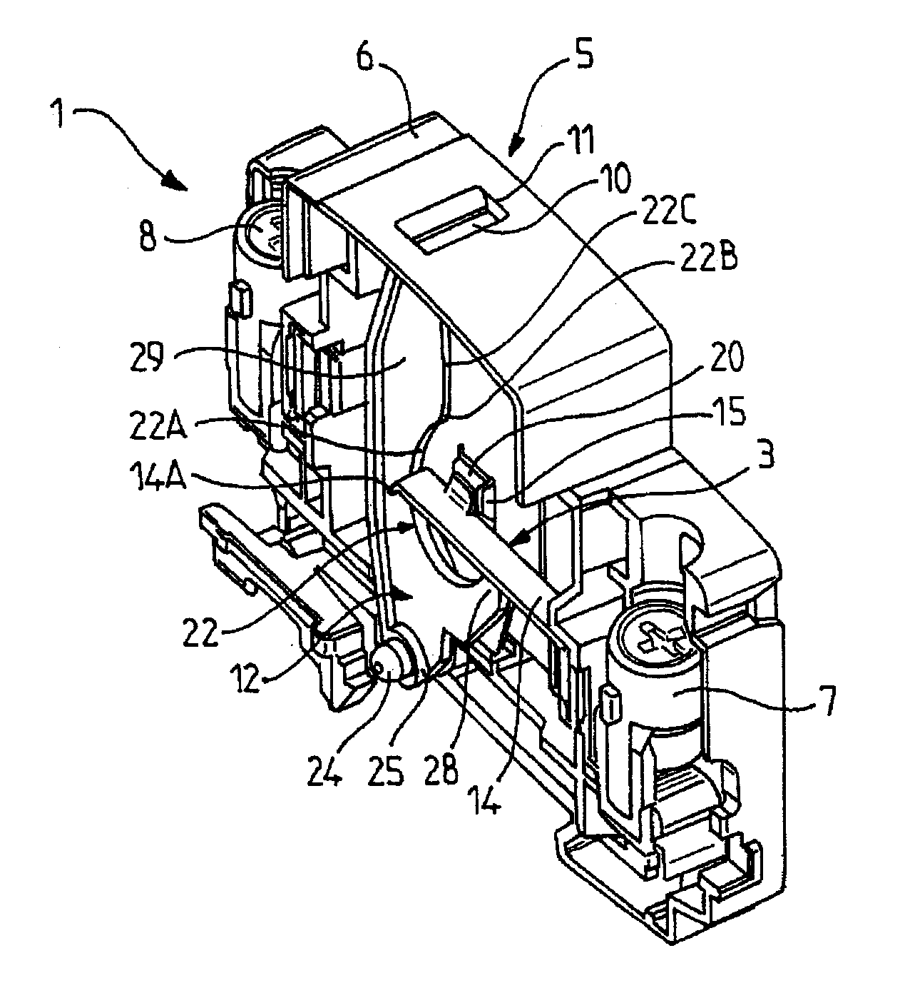
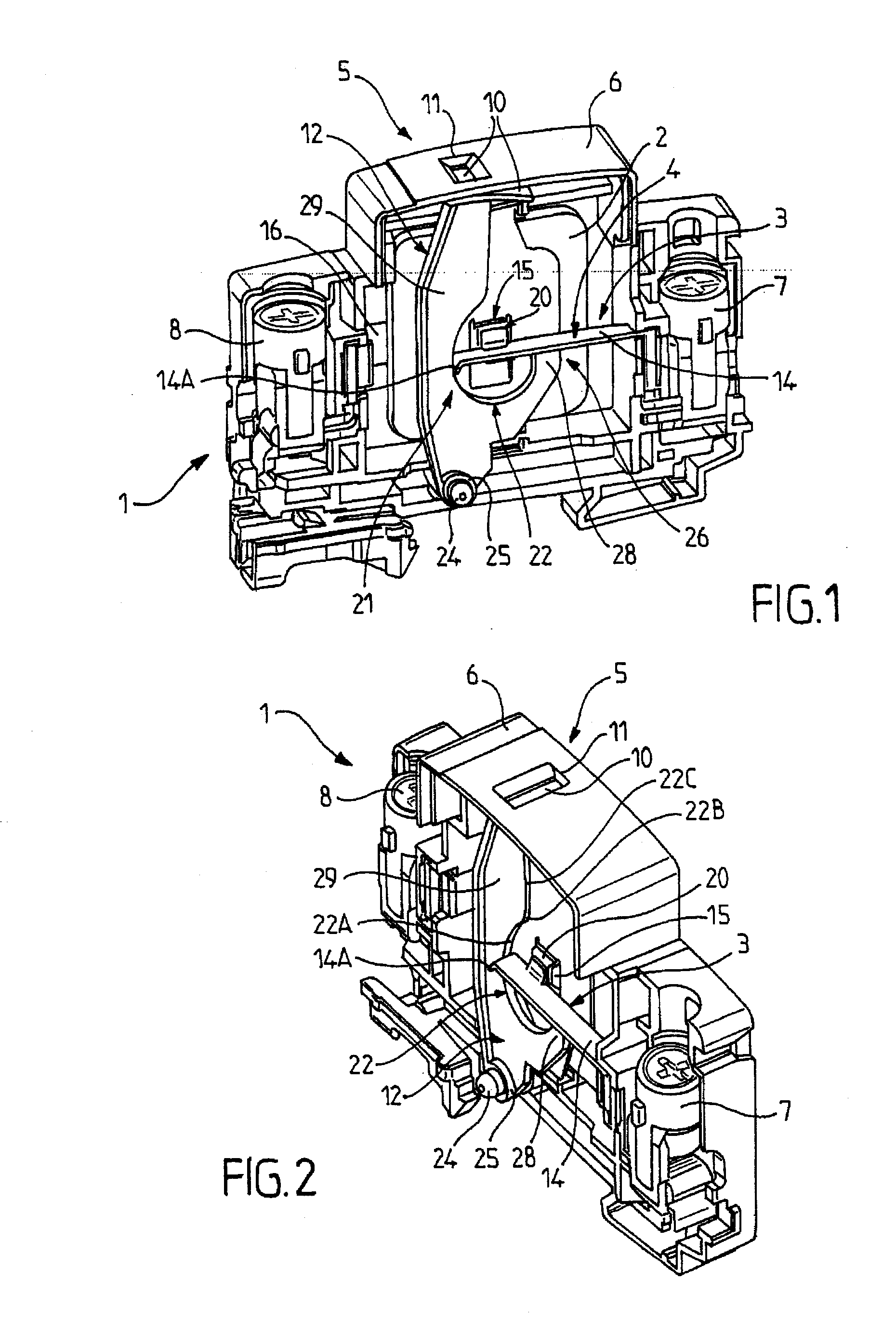
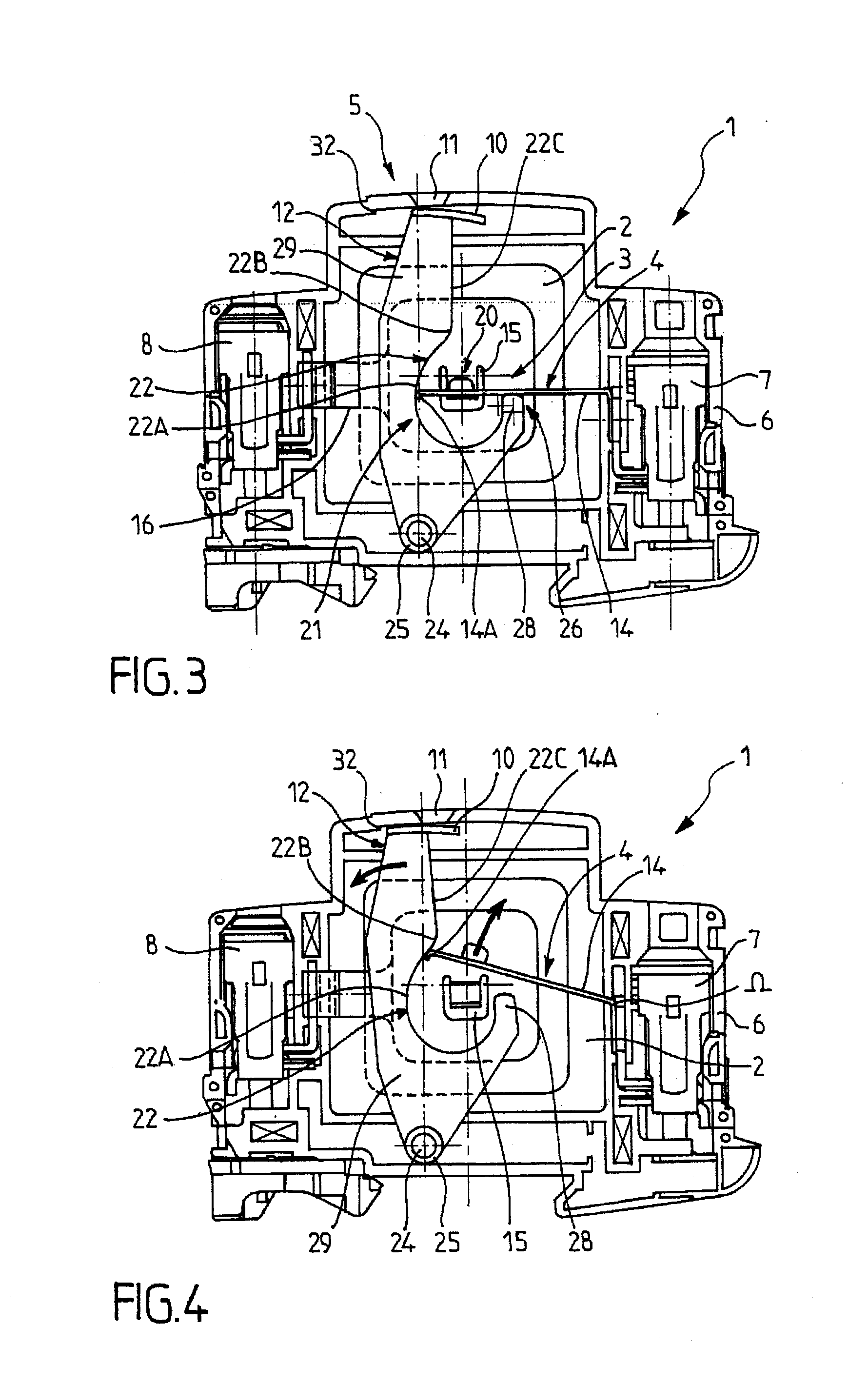
[0035] The overvoltage protection device 1 according to the present invention is intended to be shunt-connected (or connected “in parallel”) to an electrical installation to be protected.

[0036] For purposes of the present disclosure, the term “electrical installation” refers to any type of electrically powered apparatus or network capable of undergoing voltage disturbances, in particular, transient overvoltages caused by lightning.

[0037] The electrical installation overvoltage protection device 1 can advantageously be a lightning arrestor.

[0038] The overvoltage protection device 1 according to the present invention is advantageously intended to be placed between a phase of the installation to be protected and the ground. It is also possible to envisage, without going beyond the scope of the present invention, that the device 1, instead of being shunt-connected between a phase and the ground, is connected between a neutral conductor and the ground, between the phase and the neutra...


PUM


Abstract

A device (1) for protecting an electrical installation from overvoltages, having at least one protection component (2) and disconnection means (3) capable of changing from a closed configuration to an open configuration, as well as signalling means (5) capable of indicating the configuration of the disconnection means (3). The disconnection means (3) and the signalling means (5) respectively comprise a mobile disconnection element (4) and a mobile signalling element (12) arranged such that, when going from the closed configuration to the open configuration, the mobile disconnection element (4) moves in a rotational movement according to a first trajectory and cooperates with the mobile signalling element (12) to drive the mobile signalling element in rotation along a second trajectory different from the first trajectory.

Description

PRIORITY CLAIM [0001] This application claims priority to French Patent Application No. 06 01678, filed Feb. 24, 2006, the disclosure of which is incorporated herein by referenced in its entirety. FIELD OF THE INVENTION [0002] This invention relates to devices for protecting electrical installations and equipment from electrical overvoltages, especially transient overvoltages, in particular, those caused by lightning. [0003] This invention relates more specifically to a device for protecting an electrical installation from overvoltages. [0004] This invention also relates to a method for producing a device for protecting an electrical installation from overvoltages. BACKGROUND OF THE INVENTION [0005] It is well known to use protection devices capable of protecting electrical or electronic apparatuses from overvoltages that may result, for example, from lightning. [0006] These protection devices usually comprise one or more overvoltage protection components, such as, for example, a va...

Claims


Application Information

Patent Timeline
Patent Type & Authority Applications(United States)
IPC IPC(8): H02H9/04
CPCH01C7/126H01H37/761H01H2037/763H01H83/10H01H71/04
Inventor LAGNOUX, ALAIN RENE ROBERT
Owner ABB FRANCE SAS
Why Eureka
Try Eureka