Hub Unit, Rolling Bearing Assembly and Manufacture Method Thereof, as Well as Assembling Apparatus for Rolling Bearing Assebly and Assebly Method Thereof

a technology for assembling apparatus and hub shafts, which is applied in the direction of bearing unit rigid support, forging/pressing/hammering apparatus, forging/pressing/hammering, etc. it can solve the problems of caulking cracks, the end of the hub shaft is prone to cracks, and the root portion is easy to suffer cracks, etc., to achieve high accuracy assembling operation, increase productivity, and greater tolerance of the outside diameter

Inactive Publication Date: 2007-09-20
JTEKT CORP
View PDF14 Cites 24 Cited by
  • Summary
  • Abstract
  • Description
  • Claims
  • Application Information

AI Technical Summary

Benefits of technology

[0027] According to the assembling apparatus of this constitution, the annular member assembled by the caulking process may be prevented from being expanded so that a high-accuracy assembling operation may be accomplished. Furthermore, the annular member may be prevented from suffering deformation or cracks resulting from an excessive expansion thereof.
[0028] It is also preferred that the constraining ring comprises a plurality of separate constraining ring segments arranged in a circumferential direction. This constitution is adapted to restrict the quantity of expansion of the annular member associated with the caulking process to a constant value despite the variations of the outside diameter of the annular member. Specifically, the expansion quantity of the annular member is related with a gap defined between an inside surface of the constraining ring and the outside surface of the annular member. Hence, the greater the gap, the greater is the expansion quantity. It is a general practice to provide greater tolerances of the outside diameter of the annular member (coupler) than tolerances of the inner ring member of the bearing. On the other hand, the inside surface of the constraining ring normally has a fixed inside diameter. Therefore, the gap between the constraining ring and the annular member varies from product to product. However, the constraining ring is circumferentially divided into plural segments and hence, is adapted to vary the inside diameter thereof. That is, the constraining ring is capable of accommodating the tolerances of the outside diameter of the annular member. Accordingly, the apparatus permits the assembling operation to be carried on without exchanging the constraining rings, achieving an increased productivity. The apparatus may favorably be applied to mass production of the bearing assembly.
[0029] It is also preferred that the constraining ring segment is allowed to move radially without varying the angle of an inside abutment surface thereof relative to an axis of the inner shaft. According to the constitution, the inside abutment surface of the constraining ring segment may be constantly held in face contact against the outside surface of the annular member. Thus, the expansion of the annular member is prevented and besides, the annular member is assuredly prevented from being tilted. If the inside abutment surface of the constraining ring is tilted relative to the axis of the inner shaft (the angle of the inside abutment surface relative to the axis of the inner shaft is varied) when the constraining ring is decreased in the diameter to constrain the annular member, the constraining ring makes linear contact against the annular member so as to hold the annular member unstably. What is more, the annular member is tilted when subjected to a circumferentially biased force. However, the invention is adapted to obviate these drawbacks.
[0030] Even in a case where the annular member is formed with the spline on the outside surface thereof, it is preferred that the inside abutment surface of the constraining ring brought into contact against the outside surface of the annular member is defined by a smooth surface. The reason is that the spline has higher dimensional accuracies at a distal end side thereof than at a bottom thereof and hence, the deformation of the annular member may be corrected by bringing the inside abutment surface of the constraining ring into contact against the distal end side of the annular member. This also leads to an improved roundness of the annular member.
[0031] According to the invention for achieving the second object, a method of assembling a bearing assembly comprises the steps of fitting an annular member on an outside surface of an end of an inner shaft having an inner ring member fitted thereon, and radially outwardly caulking an outer-peripheral end of the inner shaft thereby fixing the annular member and the inner ring member to the inner shaft in an anti-fall fashion, and is characterized in that a constraining ring is brought into fitting contact against an outside surface of the annular member during the caulking process, thereby preventing the diametral expansion of the annular member. According to the assembling method of this constitution, the expansion of the annular member being assembled by the caulking process may be prevented so that the high-accuracy assembling operation may be accomplished. Furthermore, the annular member may be prevented from suffering deformation or cracks resulting from the excessive expansion thereof.
[0032] It is also preferred in this assembling method that the constraining ring comprises a plurality of separate constraining ring segments arranged in a circumferential direction and the individual constraining ring segments are moved in a diameter decreasing direction for making contact against the outside surface of the annular member. This constitution is adapted to restrict the quantity of expansion of the annular member associated with the caulking process to a constant value despite the variations of the outside diameter of the annular member. What is more, the method permits the assembling operation to be carried on without exchanging the constraining rings if the annular members are varied in the outside diameter. Hence, the method achieves an increased productivity and may be favorably applied to the mass production of the bearing assembly.

Problems solved by technology

However, there is a problem that the end of the hub shaft is prone to suffer the formation of cracks (called “caulking cracks”) at its root portion because the end of the hub shaft is radially outwardly bent in the shaft-end caulking process.
However, the use of the independent ring member leads to an increased number of components, thus resulting in a lowered production efficiency and inability to reduce costs.
The hub unit assembled by the shaft-end caulking has a specific problem that in a case where this hub unit is applied to the freewheel hub mechanism and is actually operated, for example, the hub shaft is prone to suffer the crack formation at a root portion of the bent end because stress is concentrated on the root portion.
If the annular member or the like is excessively expanded, the annular member or the like suffers the crack formation.

Method used


Image

  • Hub Unit, Rolling Bearing Assembly and Manufacture Method Thereof, as Well as Assembling Apparatus for Rolling Bearing Assebly and Assebly Method Thereof
  • Hub Unit, Rolling Bearing Assembly and Manufacture Method Thereof, as Well as Assembling Apparatus for Rolling Bearing Assebly and Assebly Method Thereof
  • Hub Unit, Rolling Bearing Assembly and Manufacture Method Thereof, as Well as Assembling Apparatus for Rolling Bearing Assebly and Assebly Method Thereof

Examples


Embodiment Construction

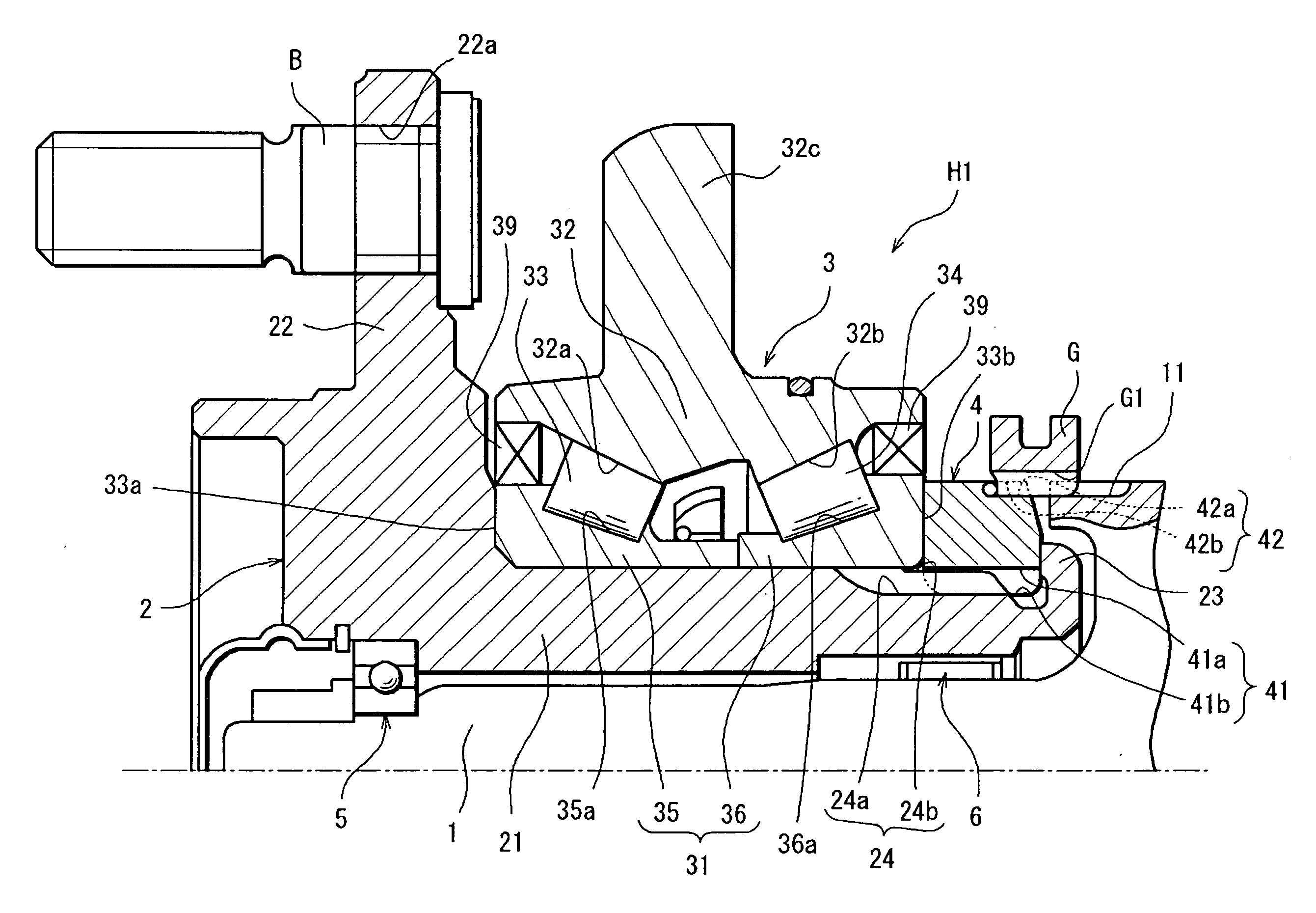
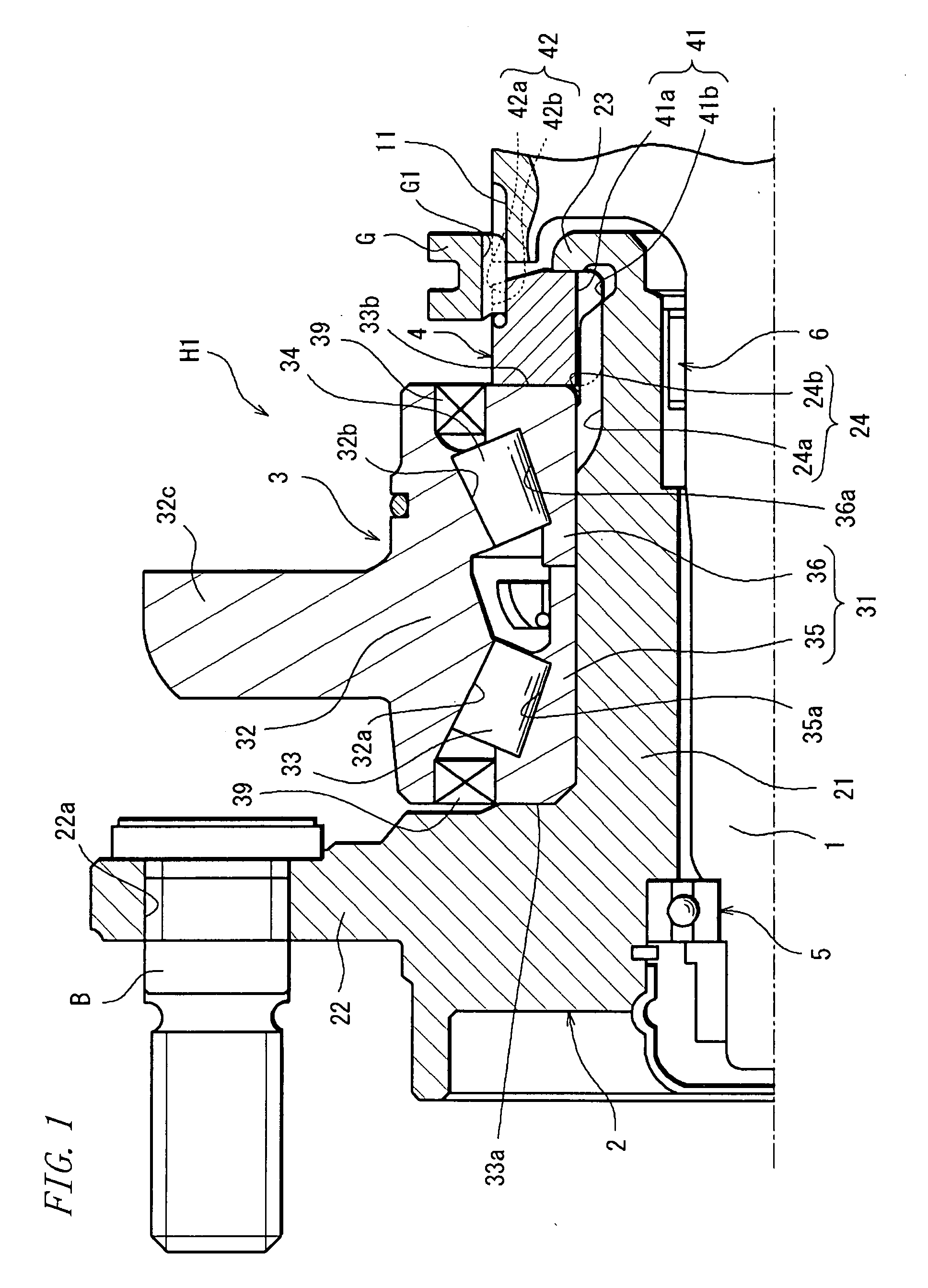
[0049] Preferred embodiments of the invention will hereinbelow be described with reference to the accompanying drawings. FIG. 1 is a sectional view showing a hub unit according to a first embodiment of the invention. A hub unit H1 according to the invention is used in, for example, a freewheel hub mechanism of a part-time 4WD vehicle. The freewheel hub mechanism includes: a hub shaft 2 coaxially mounted on an axle shaft 1 of a driving system; a double-row tapered roller bearing 3 as a rolling bearing fitted on an axially intermediate portion of the hub shaft 2; and a coupler ring 4 (annular member) axially juxtaposed to this double-row tapered roller bearing 3. The hub unit H1 is rotatably carried by a deep groove ball bearing 5 and a needle roller bearing 6 in a coaxial relation with the axle shaft 1 (carried in a manner to be circumferentially rotatable relative to the axle shaft 1), the deep groove ball bearing 5 and the needle roller bearing 6 interposed between the axle shaft 1...


PUM

PropertyMeasurementUnit
lengthaaaaaaaaaa
lengthaaaaaaaaaa
lengthaaaaaaaaaa

Abstract

A rolling bearing adapted to prevent crack formation in a caulking portion is provided. A rolling bearing assembly includes: a hub shaft having the caulking portion at an axial end thereof, the caulking portion bendably deformed in a radially outward direction; the rolling bearing mounted on an outside surface of the hub shaft; and an annular member spline-engaged with the hub shaft and caulk-fixed to place by the caulking portion. An inner-side axial end of a second male spline formed on the hub shaft is shifted from an inner-side end of the hub shaft toward an outer side far enough to ensure that the second male spline is not susceptible to the plastic deformation of the caulked caulking portion.

Description

[0001] Hub unit, rolling bearing assembly and manufacture method thereof, as well as assembling apparatus for rolling bearing assembly and assembly method thereof. TECHNICAL FIELD [0002] The present invention relates to a hub unit for use in an automotive freewheel hub mechanism, for example, a rolling bearing assembly for use in the hub unit mounted to an automotive vehicle or the like, and a manufacture method thereof. The invention also relates to an assembling apparatus for bearing assembly which assembles an annular member by caulking an end of an inner shaft and an assembling method thereof. BACKGROUND ART [0003] A full-time 4WD vehicle and a part-time 4WD vehicle are known as four-wheel drive vehicles. The part-time 4WD vehicle is a vehicle adapted for shifting between a 2WD drive mode and a 4WD drive mode. This four-wheel drive vehicle is designed to bring driven wheels into a free state by disconnecting, for example, the driven wheels from an axle shaft of a driving system,...

Claims


Application Information

Patent Timeline
Patent Type & Authority Applications(United States)
IPC IPC(8): F16C35/00F16C13/00
CPCB60B27/001F16C19/386F16C35/063F16C2326/02F16C19/186B60B27/06F16C2240/40B21J9/025B21K25/00F16C43/04B60B35/18B21D39/00
Inventor KASHIWAGI, SHINICHIROUTAKASAKI, SHINNOSUKENAKAGAWA, YUICHIKAMIKAWA, TSUYOSHIDEGUCHI, MASARUINOUE, MASAHIRO
Owner JTEKT CORP
Why Eureka
Try Eureka