
Modular chest drainage design and assembly method

a chest drainage and module technology, applied in the field of medical devices, can solve the problems of increasing construction and manufacturing costs, affecting the quality reducing the efficiency of the whole device, so as to achieve the effect of robustness and cost-effectiveness

Inactive Publication Date: 2007-09-20
TELEFLEX MEDICAL INC
View PDF18 Cites 5 Cited by
  • Summary
  • Abstract
  • Description
  • Claims
  • Application Information

AI Technical Summary

Benefits of technology

[0009] The foregoing needs are met, to a great extent, by the present invention, wherein in one aspect an apparatus is provided that in some e...

Problems solved by technology

One problem with the existing Pleur-evac® system and other known chest drainage devices and assemblies is that, due to the large number of constituent functioning elements in the device, such as the water seal, suction control, pressure or indicator manometer, and the like, when any one part of the overall assembly fails, the entire device is rendered useless.
That is, because of the unitary construction and assembly of the chest drainage devices, replacement, repair, or redesign of any one component of the assembly is difficult.
In addition, the unitary structure of the known chest drainage devices leads to increased construction and manufacturing costs, as large molds need to be made to produce the devices, which can be very expensive to replace or alter should the design of the apparatus change.
However, this device has each of the chambers, which are separate bodies, connected solely to each other and requires a specific type of structural connection between the chambers.
The plastic tubing has the possibility of ceasing to maintain the desired seal between the chambers so that the aseptic environment may be lost.
However the prior art discussed above still has several drawbacks and presents numerous disadvantages.
First, the known modular assemblies are overly complex and involve unnecessary parts and elements which can lead to failure or malfunctioning of the device.
Further, the method of assembly and manufacture of the various elements of the known chest drainage devices is too expensive and time-consuming.
Such back or base molds can be large and very expensive.
Changes or repairs to the mold are difficult because of production requirements.
Repairs and modifications are very difficult due to the size and complexity of the mold.

Method used


Image

  • Modular chest drainage design and assembly method
  • Modular chest drainage design and assembly method
  • Modular chest drainage design and assembly method

Examples


Embodiment Construction

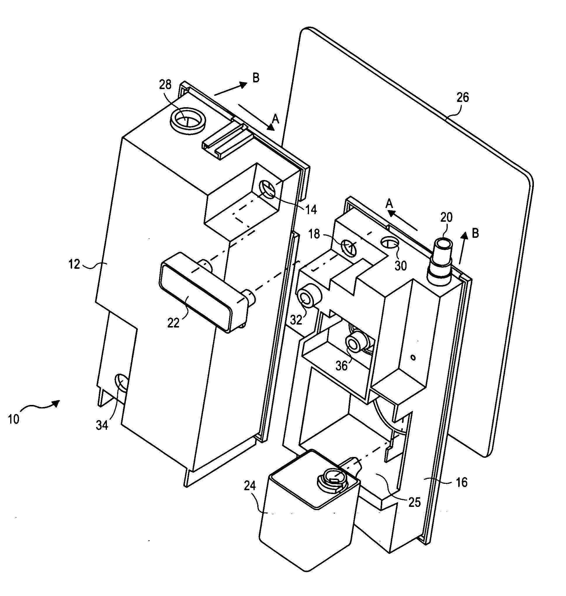
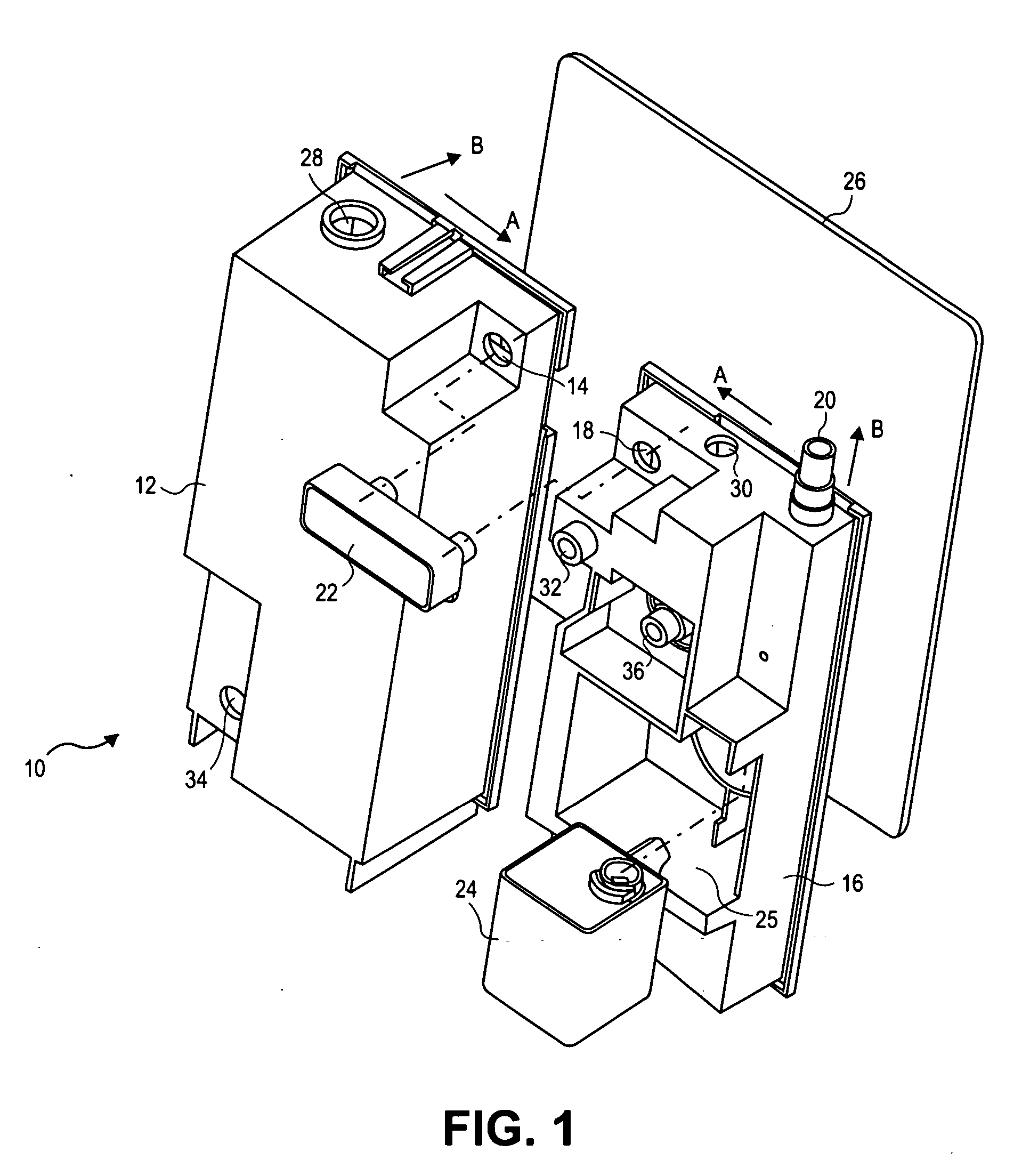
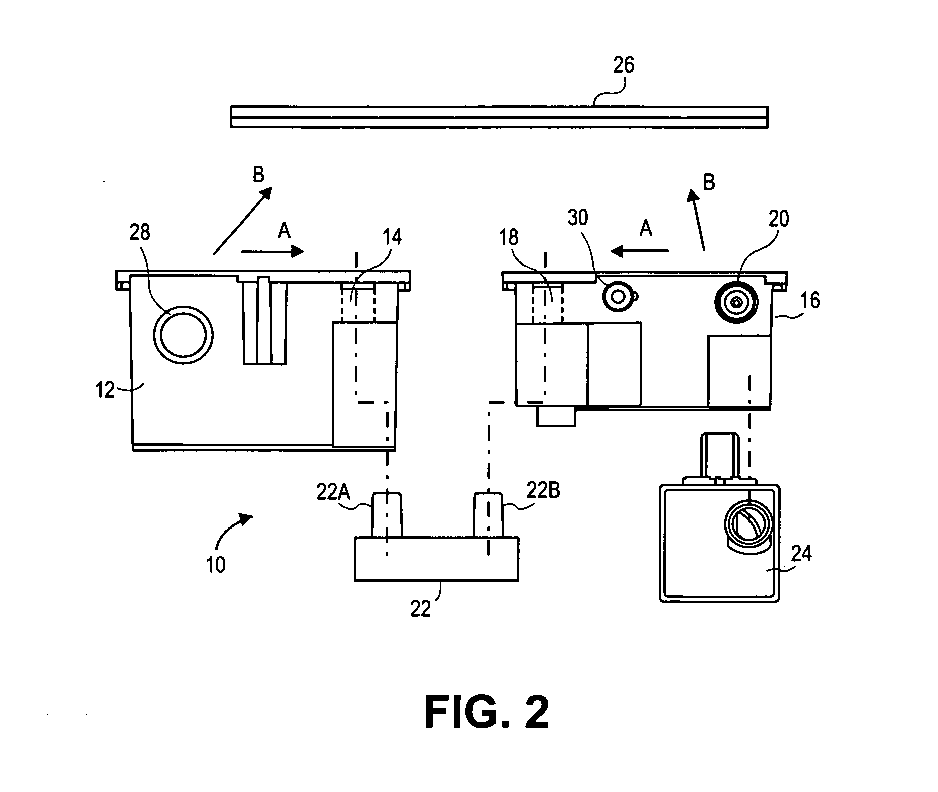
[0021] The invention will now be described with reference to the drawing figures, in which like reference numerals refer to like parts throughout. An embodiment in accordance with the present invention provides a modular chest drainage device including several components or modules which can be separately designed, made, and then assembled together. The modules include a collection module having a collection chamber which includes a flow intake port for receiving body fluids from a patient, such as blood or air from a pleural cavity during chest surgery. Further included is a “flow control” module having one or more flow passageways, valves, water seals, manometers, check valves, or other flow control elements which can be used to control the flow, pressure, and other conditions in the overall apparatus, including the collection chamber of the collection module. The flow control module has a suction port that can be coupled to a source of suction which provides the source means for ...


PUM


Abstract

A modular chest drainage assembly is provided, having a collection module formed from a first base mold. The collection module defines a collection chamber having a patient fluid intake port. The assembly further includes a flow control module formed from a second base mold. A separate flow coupling is attachable to the collection module and flow control module to place the two modules in fluid communication. A pre-assembled pressure regulation module is coupled to the flow control module to regulate the pressure inside the collection module and flow control module. The assembly further includes a face plate, to which the collection module and flow control module are bonded such that the flow control module defines a first fluid flow pathway from the flow coupling to a suction port on the flow control module, for transmitting a suction flow from the collection chamber to the suction port.

Description

FIELD OF THE INVENTION [0001] The present invention relates generally to medical devices. More particularly, the present invention relates to a chest drainage apparatus and method of assembly thereof. BACKGROUND OF THE INVENTION [0002] Chest drainage devices and systems and more particularly suction drainage systems and devices for removing gases and / or liquids from medical patients, such as from the pleural cavity, by means of a pressure differential, are well known in the art. For many years, the standard apparatus for performing the evacuation of the pleural cavity was a drainage system known as the “3-bottle set-up” which includes a collection bottle, a water seal bottle, and a suction control bottle. A catheter runs from the patient's pleural cavity to the collection bottle, and the suction bottle is connected by a tube to a suction source. The three bottles are connected in series by various tubes to apply suction to the pleural cavity to withdraw fluid and air and thereafter ...

Claims


Application Information

Patent Timeline
IPC IPC(8): A61M27/00
CPCA61M2205/3379A61M1/0013A61M1/61
Inventor PHUNG, TRINH D.DREYER, ERICH A.MOORE, DOUGLAS W.
Owner TELEFLEX MEDICAL INC
Learn More