Storage system and storage system control method

a storage system and control method technology, applied in the field of storage system and storage system control method, can solve the problems of lowering usability, reducing response performance, and reducing the usefulness of pre-reading data using prefetch, so as to prevent sequential access response performance, improve usability, and improve response performance

Inactive Publication Date: 2007-09-20
HITACHI LTD
View PDF3 Cites 34 Cited by
  • Summary
  • Abstract
  • Description
  • Claims
  • Application Information

AI Technical Summary

Benefits of technology

[0014] With the foregoing in mind, an object of the present invention is to provide a storage system and storage system control method that make it possible to improve the response performance of sequential access to data that is expected to be read out sequentially. A further object of the present invention is to provide a storage system and storage system control method that make it possible to prevent sequential access response performance from dropping below a predetermined value even when the continuity of the data arrangement has been lost, enabling improved usability. Other objects of the present invention should become clear from the disclosure of the embodiments, which will be explained hereinbelow.

Problems solved by technology

Because of this, it takes time before the content can be played back, lowering usability.
However, this first prior art is premised on the fact that the data is arranged sequentially on a recording medium, and does not take into consideration cases in which the data is not sequentially arranged on a recording medium.
The more data fragmentation progresses, the more useless the pre-reading of data using prefetch becomes, and the more response performance is lowered.
That is, the first prior art is only effective for extremely limited applications, and has low usability.
However, the second prior art is premised on a single sequential access, and cannot support multiple sequential accesses, in which a plurality of sequential accesses is generated simultaneously.
That is, the second prior art cannot demonstrate its effect unless the number of streams is limited to a single stream.

Method used


Image

  • Storage system and storage system control method
  • Storage system and storage system control method
  • Storage system and storage system control method

Examples


first embodiment

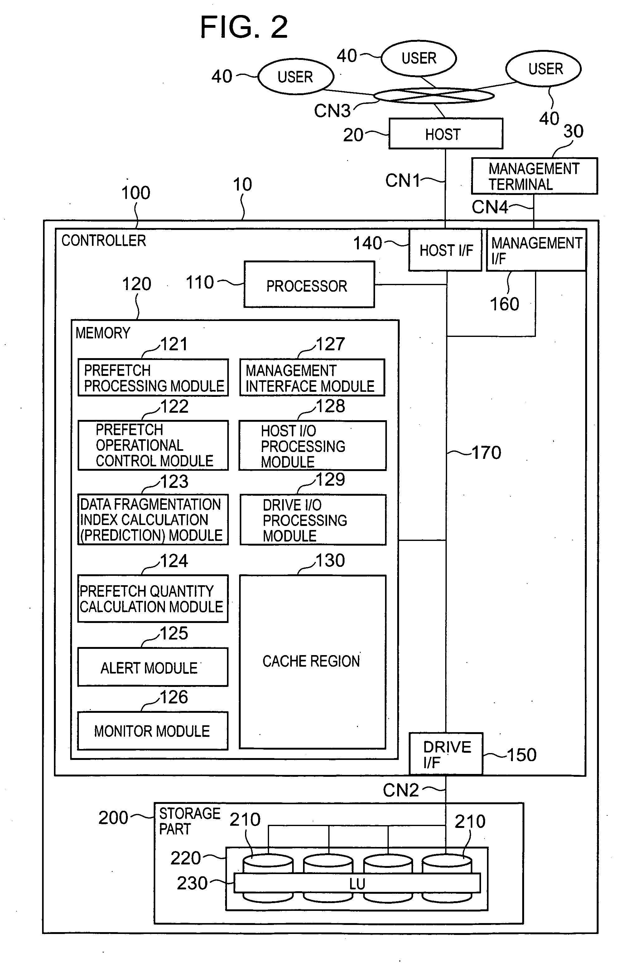
[0084]FIG. 2 is a schematic diagram showing the overall constitution of a storage system 10 according to this embodiment. The storage system 10, for example, can be constituted comprising a controller 100 and a storage part 200. The storage system 10 is connected to at least one or more hosts 20.

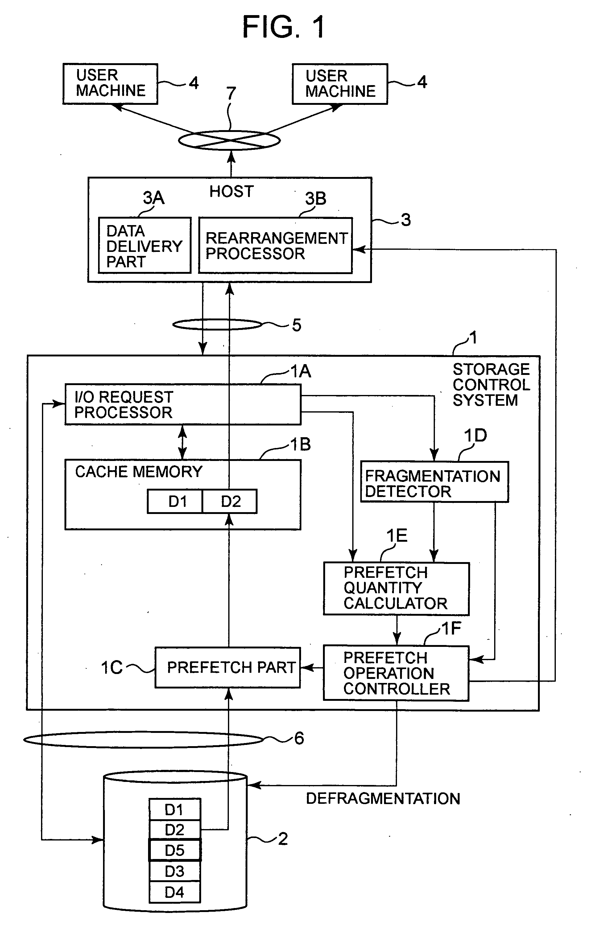
[0085] First, the corresponding relationship between FIG. 1 and FIG. 2 will be described. The controller 100 corresponds to the storage control device 1, the storage part 200 corresponds to the storage part 2, the host 20 to the host 3, the user machine 40 to the user machine 4, the communication channel CN1 to the communication channel 5, the communication channel CN2 to the communication channel 6, and the communication network CN3 to the communication network 7, respectively.

[0086] The storage system 10, for example, is connected to the host 20 via the communication channel CN1 of a SAN or LAN. The host 20 is connected to each of a plurality of user machines 40 via the communication net...

second embodiment

[0209] A second embodiment will be explained on the basis of FIGS. 13 and 14. The following embodiments, to include this embodiment, correspond to variations of the first embodiment. In this embodiment, only the ON / OFF of the prefetch function is controlled without adjusting the value of the prefetch quantity DP.

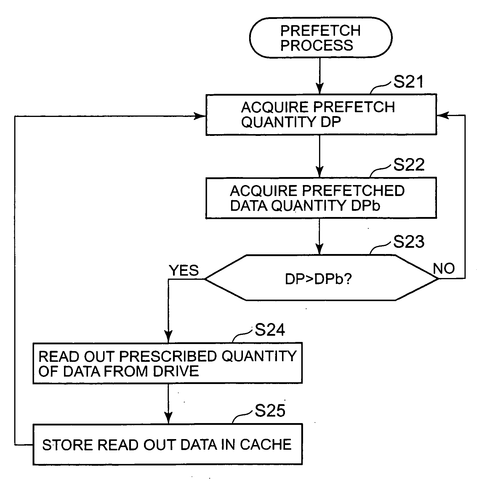
[0210]FIG. 13 is a flowchart showing a prefetch operational control process according to this embodiment. With the exception of S33, this flowchart comprises all the steps from S31 through S41 included in the flowchart shown in FIG. 5.

[0211] That is, in the prefetch operational control process of this embodiment, the prefetch quantity DP is not updated based on a data fragmentation index FI. The prefetch quantity DP is fixed as-is, and only the ON / OFF of the prefetch function is controlled.

[0212]FIG. 14 shows the response performance characteristics of the storage system 10 in accordance with this embodiment. As can be seen by comparing FIG. 14 with FIG. 12 (a), since the...

third embodiment

[0214] A third embodiment will be explained based on FIG. 15. In this embodiment, prefetch operational control does not commence until the statistical information required for carrying out the prefetch operational control described in the first embodiment has been stored.

[0215]FIG. 15 is a flowchart showing the process for starting up prefetch operational control. The controller 100 uses the monitor module 126 to make a determination as to whether or not the statistical information needed to carry out the control of a prefetch operation (prefetch quantity setting, prefetch function ON / OFF) has been collected (S91). As examples of statistical information, the cache hit rate, read access time, and size of the data being read accessed can be cited.

[0216] When sufficient statistical information has been stored to commence prefetch operational control (S91: YES), the controller 100 determines whether or not user (host administrator) approval has been obtained for commencing prefetch op...


PUM


Abstract

A storage system of the present invention improves the response performance of sequential access to data, the data arrangement of which is expected to be sequential. Data to be transmitted via streaming delivery is stored in a storage section. A host sends data read out from the storage section to respective user machines. A prefetch section reads out from the storage section ahead of time the data to be read out by the host, and stores it in a cache memory. A fragmentation detector detects the extent of fragmentation of the data arrangement in accordance with the cache hit rate. The greater the extent of the fragmentation, the smaller the prefetch quantity calculated by a prefetch quantity calculator. A prefetch operation controller halts a prefetch operation when the extent of data arrangement fragmentation is great, and restarts a prefetch operation when the extent of fragmentation decreases.

Description

CROSS-REFERENCE TO RELATED APPLICATION(S) [0001] This application relates to and claims priority from Japanese Patent Application No. 2006-70224 filed on Mar. 15, 2006, the entire disclosure of which is incorporated herein by reference. BACKGROUND OF THE INVENTION [0002] 1. Field of the Invention [0003] The present invention relates to a storage system and a storage system control method. [0004] 2. Description of the Related Art [0005] In recent years, for example, technology for delivering video, voice and other content data in the form of movies, plays, news stories, and educational programming directly to users via networks has begun to become popular. At this point, the methods for supplying content data to users can be broadly divided into downloading systems and streaming systems. [0006] In the case of downloading systems, the entire content data is stored on a user's computer, after which it becomes possible to view this content data. Because of this, it takes time before the...

Claims


Application Information

Patent Timeline
Patent Type & Authority Applications(United States)
IPC IPC(8): G06F12/00
CPCG06F12/0862G06F2212/6026G06F12/0866
Inventor NOMURA, KENMINE, HIROSHI
Owner HITACHI LTD
Why Eureka
Try Eureka