Image monitoring system and image monitoring program

a monitoring system and image technology, applied in the field of image monitoring system and image monitoring program, can solve the problems of complicated operation, time-consuming operation, etc., and achieve the effect of easy and simple image monitoring setup

Active Publication Date: 2007-09-20
SONY CORP
View PDF2 Cites 42 Cited by
  • Summary
  • Abstract
  • Description
  • Claims
  • Application Information

AI Technical Summary

Benefits of technology

[0010] Because an allocation database containing the correlation between the window in a predetermined layout and a camera identification code is preset, connecting a camera to a network allows the automatic setting of the correlation between the camera identification code in the allocation database and the networked camera. Consequently, when a camera is connected to a network, the camera identification code related with the networked camera can be displayed in the window of a selected layout without executing any special allocating operation.
[0011] As described above and according to the embodiments of the present invention, by only connecting a camera to a network instantly allows the displaying of camera images into a window of a predetermined layout, thereby eliminating the necessity of the manual allocation of cameras by the user. Hence, by only connecting a camera to a network, the user can display images captured by a camera onto a display monitor without executing time and labor consuming operations, thereby realizing a significantly easy and simple image monitoring setup.

Problems solved by technology

These operations are very time and labor consuming.
Especially, if there are many prepared layouts, many layouts must be allocated to one camera, thereby presenting problems of complicated operations in realizing a significantly simple and easy image monitoring setup.

Method used


Image

  • Image monitoring system and image monitoring program
  • Image monitoring system and image monitoring program
  • Image monitoring system and image monitoring program

Examples


Embodiment Construction

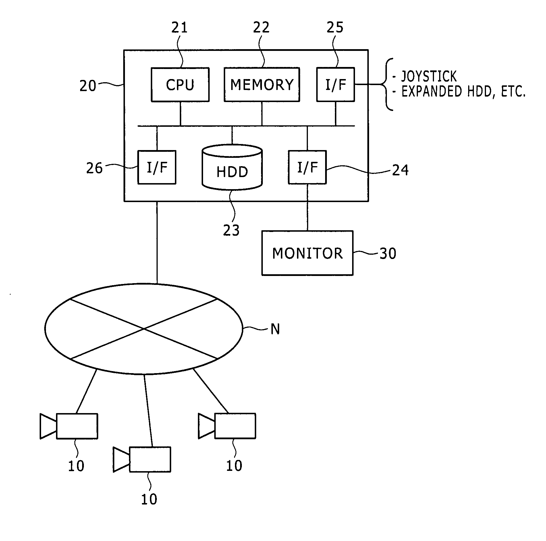
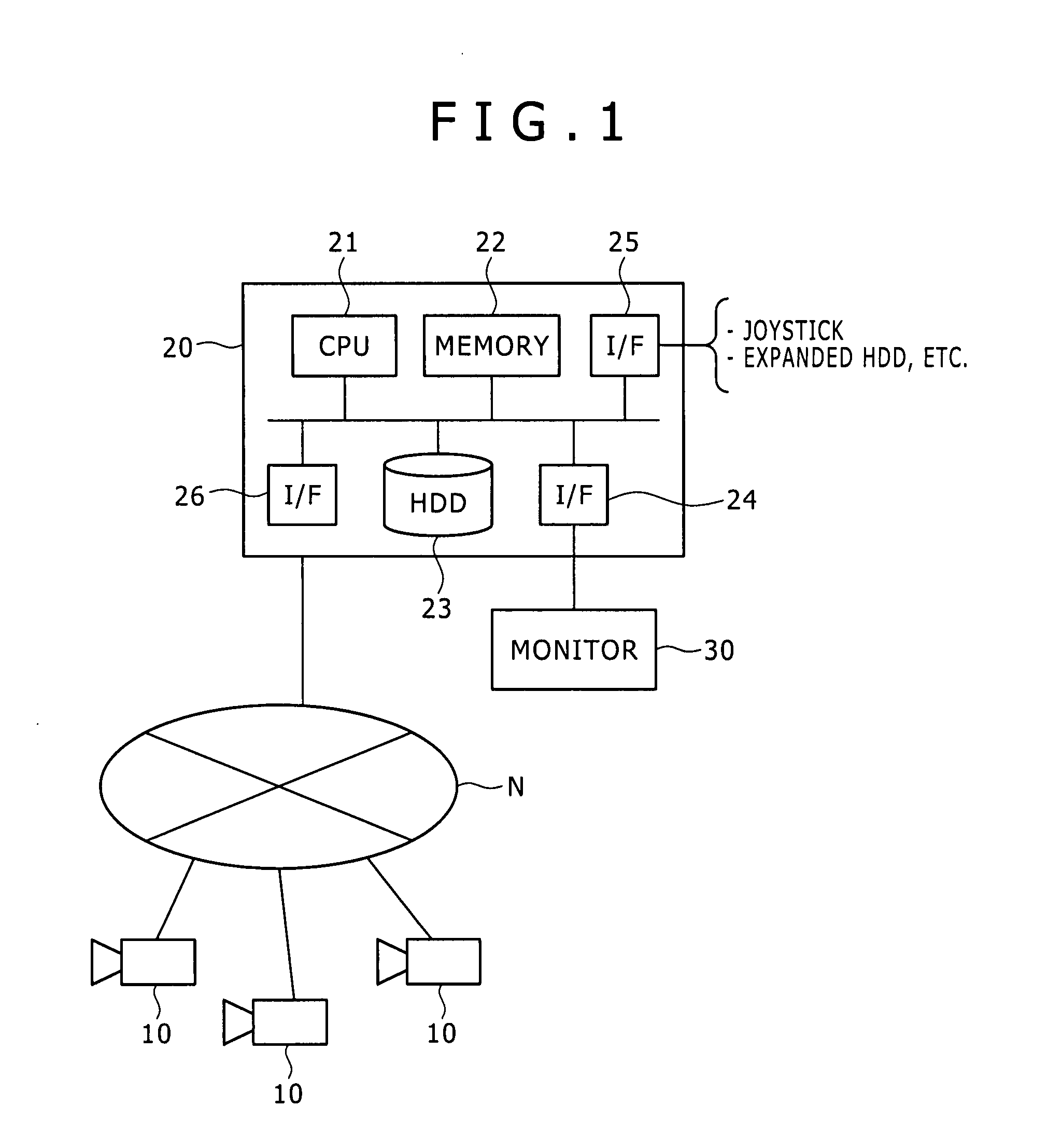
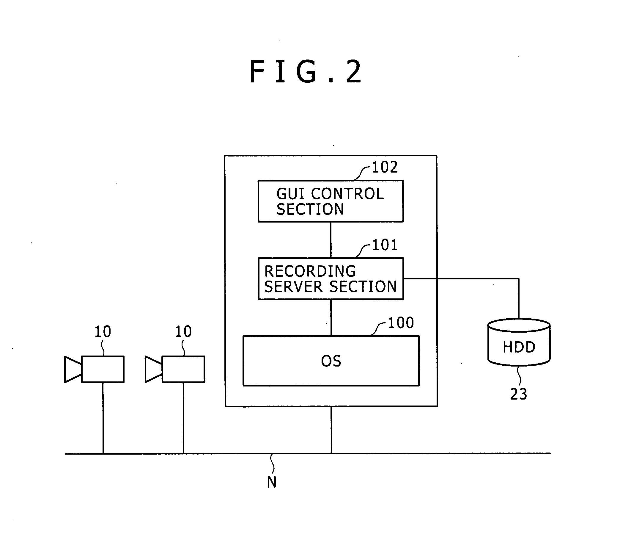
[0024] This invention will be described in further detail by way of embodiments thereof with reference to the accompanying drawings. Now, referring to FIG. 1, there is shown a schematic diagram illustrating an exemplary configuration of an image monitoring system according to an embodiment of the present invention. Referring to FIG. 2, there is shown a schematic diagram illustrating an exemplary configuration of an image monitoring program according to another embodiment of the present invention.

[0025] As shown in FIG. 1, an image monitoring system according to the present embodiment includes a camera 10 (or cameras 10) connected to a network N, a monitoring apparatus 20 connected to the same network N, and a monitor (or a display section) 30 connected to the monitoring apparatus 20. In this image monitoring system, an image captured by the camera 10 is transmitted to the monitoring apparatus 20 via the network N in a predetermined data format (for example, JPEG (Joint Photographic...


PUM


Abstract

Disclosed herein is an image monitoring system including: a camera connected to a network; display means for displaying an image captured by the camera; and display control means for controlling display such that, in displaying images by the display means, an image is displayed in a window having a predetermined layout; wherein the display control means presets an allocation database containing a correlation between the window having a predetermined layout and a camera identification code and, when the camera is connected to the network, automatically sets a correlation between the camera identification code in the allocation database and the camera, thereby controlling image display into the window on the basis of the allocation database.

Description

CROSS REFERENCES TO RELATED APPLICATIONS [0001] The present invention contains subject matter related to Japanese Patent Application JP 2006-059026 filed in the Japanese Patent Office on Mar. 6, 2006, the entire contents of which being incorporated herein by reference. BACKGROUND OF THE INVENTION [0002] 1. Field of the Invention [0003] The present invention relates to an image monitoring system and an image monitoring program that can display, in a predetermined layout, image taken by a camera connected to a network and record and reproduce the image captured from that camera. [0004] 2. Description of the Related Art [0005] Image monitoring systems are used to monitor images captured from a plurality of cameras simultaneously displayed on one monitor display in a partitioned manner and record captured images to reproduce later as necessary, for example. Recently, for the purpose of enhanced security, image-based monitoring activities are practiced in various places, such as company ...

Claims


Application Information

Patent Timeline
Patent Type & Authority Applications(United States)
IPC IPC(8): H04N7/173H04N7/18
CPCG08B13/19682H04N7/18G06F3/0481H04N7/181H04N23/661H04N23/63H04N23/62H04N7/0806H04N9/87
Inventor ISHII, SATOSHI
Owner SONY CORP
Why Eureka
Try Eureka