

Variable case depth powder metal gear and method thereof
- Summary
- Abstract
- Description
- Claims
- Application Information
AI Technical Summary
Benefits of technology
Problems solved by technology
Method used
Image

Examples
Embodiment Construction
[0018] In all figures, the same reference numerals are used to identify like parts in the various views. Thus, simultaneous reference to the various figures is appropriate. In some instances, for clarity, equivalent parts in different figures may have different item numbers.
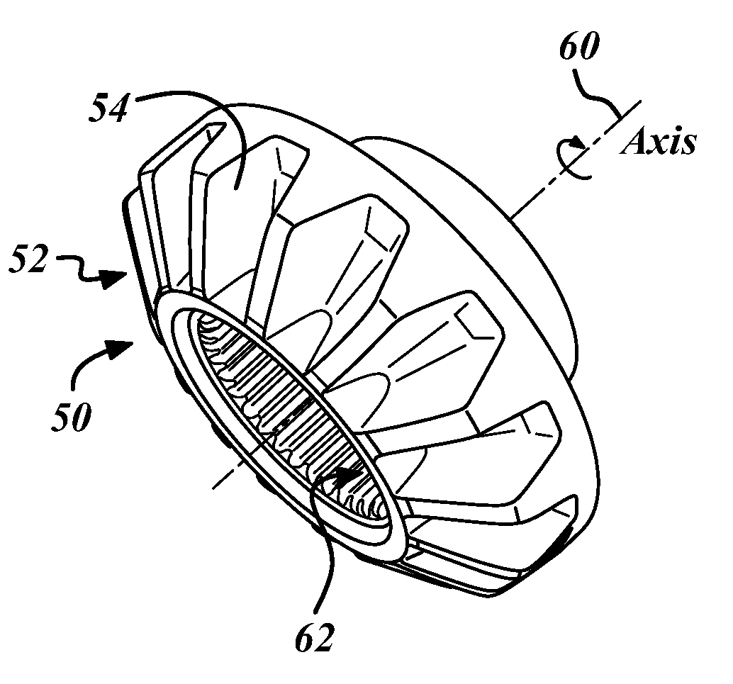
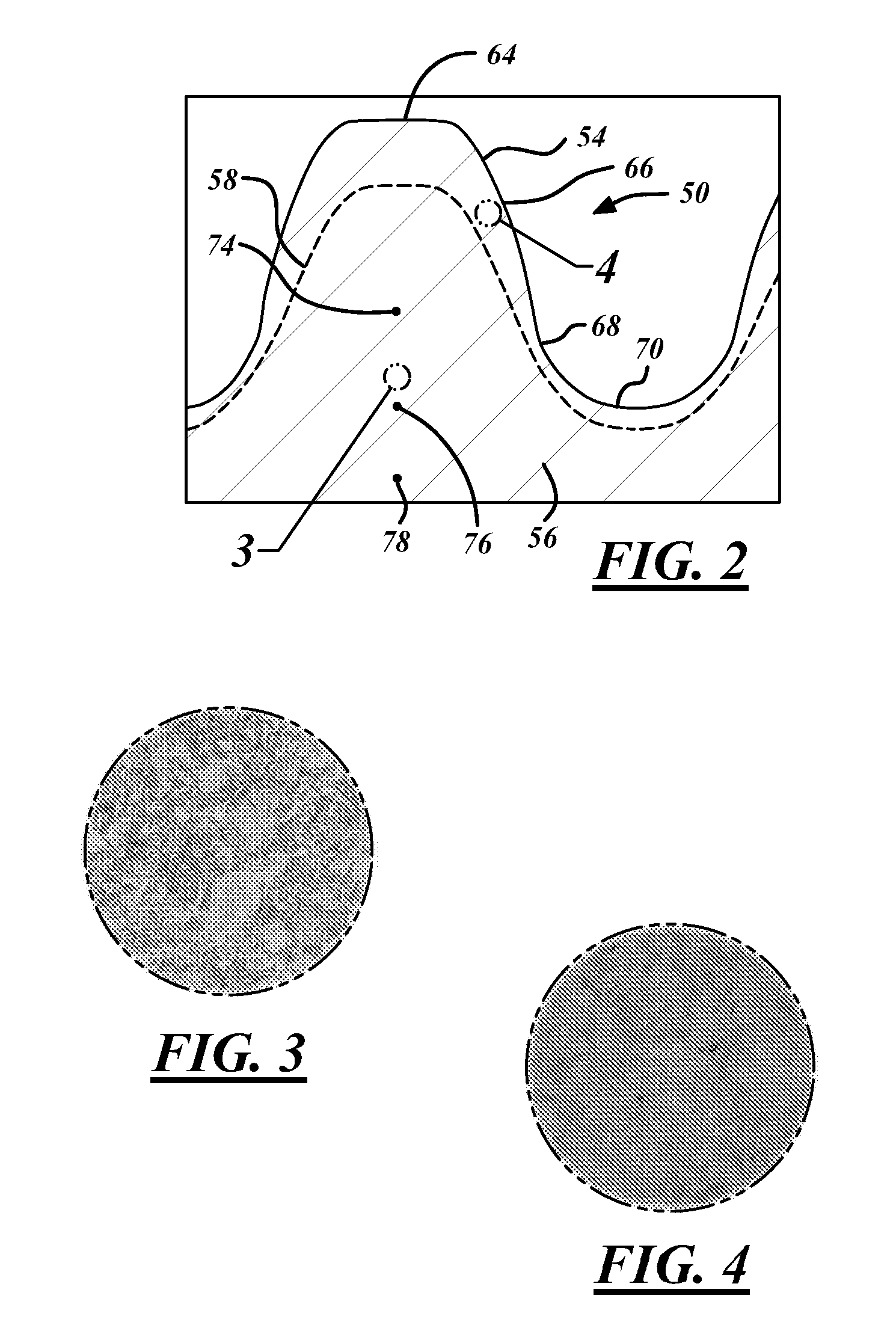
[0019]FIG. 2 shows a partial cross-sectional view of a first differential side gear 50 having a variable case depth profile 58 in accordance with an embodiment of the invention. FIG. 7 shows an isometric view of the first differential side gear 50 of FIG. 2 made from the preform 85 of FIG. 6 in accordance with an embodiment of the invention.
[0020] The first differential side gear 50 includes plurality of teeth 52 and a variable case depth profile 58. Each tooth of the plurality of teeth 52 has a first surface 54 and a tooth core or root 56. The first differential side gear 50 has a rotational axis 60, wherein the teeth 52 extend radially in the same general direction as the rotational axis of the gear, but are ...
PUM
| Property | Measurement | Unit |
|---|---|---|
| Depth | aaaaa | aaaaa |
| Depth | aaaaa | aaaaa |
| Depth | aaaaa | aaaaa |
Abstract
Description
Claims
Application Information