Electric component support structure for motorcycle

a technology for supporting structures and electric components, which is applied in the direction of machines/engines, cycle equipment, combustion air/fuel air treatment, etc., to achieve the effects of reducing weight, reducing vibration isolating support structures, and small capacity

Active Publication Date: 2007-09-27
HONDA MOTOR CO LTD
View PDF10 Cites 14 Cited by
  • Summary
  • Abstract
  • Description
  • Claims
  • Application Information

AI Technical Summary

Benefits of technology

[0013]In the electric component support structure according to the first aspect of the present invention, the throttle body, to which vibration from the engine is less likely to be transmitted, can be used to support the electric component, thus achieving an advantageous vibration isolating support structure. This allows an electric component that is not resistant to vibration to be adopted and an elastic body disposed between the electric component and the throttle body to have a small capacity. As a result, reduction in weight can be achieved.
[0014]In the electric component support structure according to the second aspect of the present invention, the throttle body is connected to the vehicle body side also via the connecting tube made of an elastic body. As a result, vibration from the vehicle body is less likely to be transmitted, making the structure an even more advantageous vibration isolating support structure.
[0015]In the electric component support structure according to the third aspect of the present invention, the capacitor as an electric component is supported onto the throttle body via the holder formed from an elastic material covering the capacitor. Accordingly, elasticity of the holder is added to elasticity of the insulator and the connecting tube supporting the throttle body onto the engine and the vehicle body side, respectively. The capacitor is thus elastically supported. Support offering an even greater vibration isolation performance can therefore be provided for the capacitor that is susceptible to vibration.
[0016]In the electric component support structure according to the fourth aspect of the present invention, the electric component is supported downward relative to the throttle body which is elastically supported onto the engine and the vehicle body side via the insulator and the connecting tube. This permits mounting of the electric component in a condition, in which vibration is less likely to be transmitted to the electric component. At the same time, a space surrounded by the throttle body, the cylinder, and the crankcase can be used effectively. This results in enhanced space utilization efficiency in layout of the electric component.
[0017]In the electric component support structure according to the fifth aspect of the present invention, the electric component can be supported by making use of the throttle body cover that is mounted to the throttle body. This eliminates the need for a dedicated electric component support member. As a result, the number of parts used can be reduced and the support structure can be simplified. Moreover, the electric component can be covered with the throttle body cover, which blocks off heat from the engine for the electric component.
[0018]In the electric component support structure according to the sixth aspect of the present invention, the throttle body cover is previously divided into left- and right-hand side halves and then the left- and right-hand side halves are mounted so as to sandwich the throttle body. The left- and right-hand side halves are further connected together at a connection downward of the throttle body during mounting. Accordingly, the electric component can be easily supported by simply inserting the connection into the slit previously formed on the side of the electric component.

Problems solved by technology

A problem with the known arrangement is that, because the electric components are fixed to the engine, it is necessary to adopt electric components that offer high vibration resistance or to dispose an elastic member having a large capacity between the electric components and the engine.

Method used


Image

  • Electric component support structure for motorcycle
  • Electric component support structure for motorcycle
  • Electric component support structure for motorcycle

Examples


Embodiment Construction

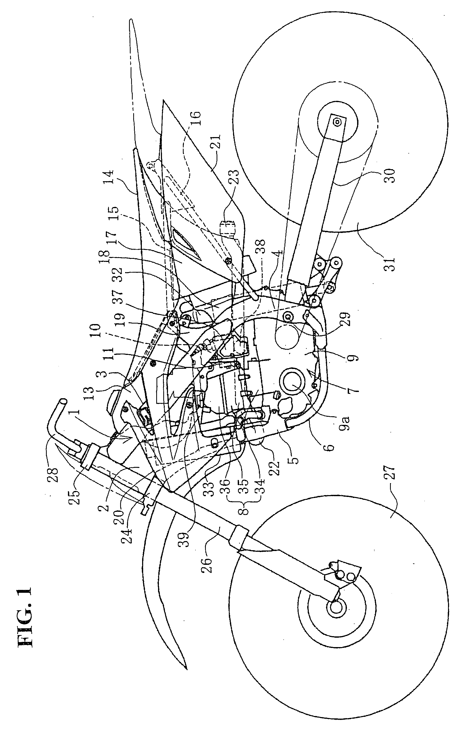
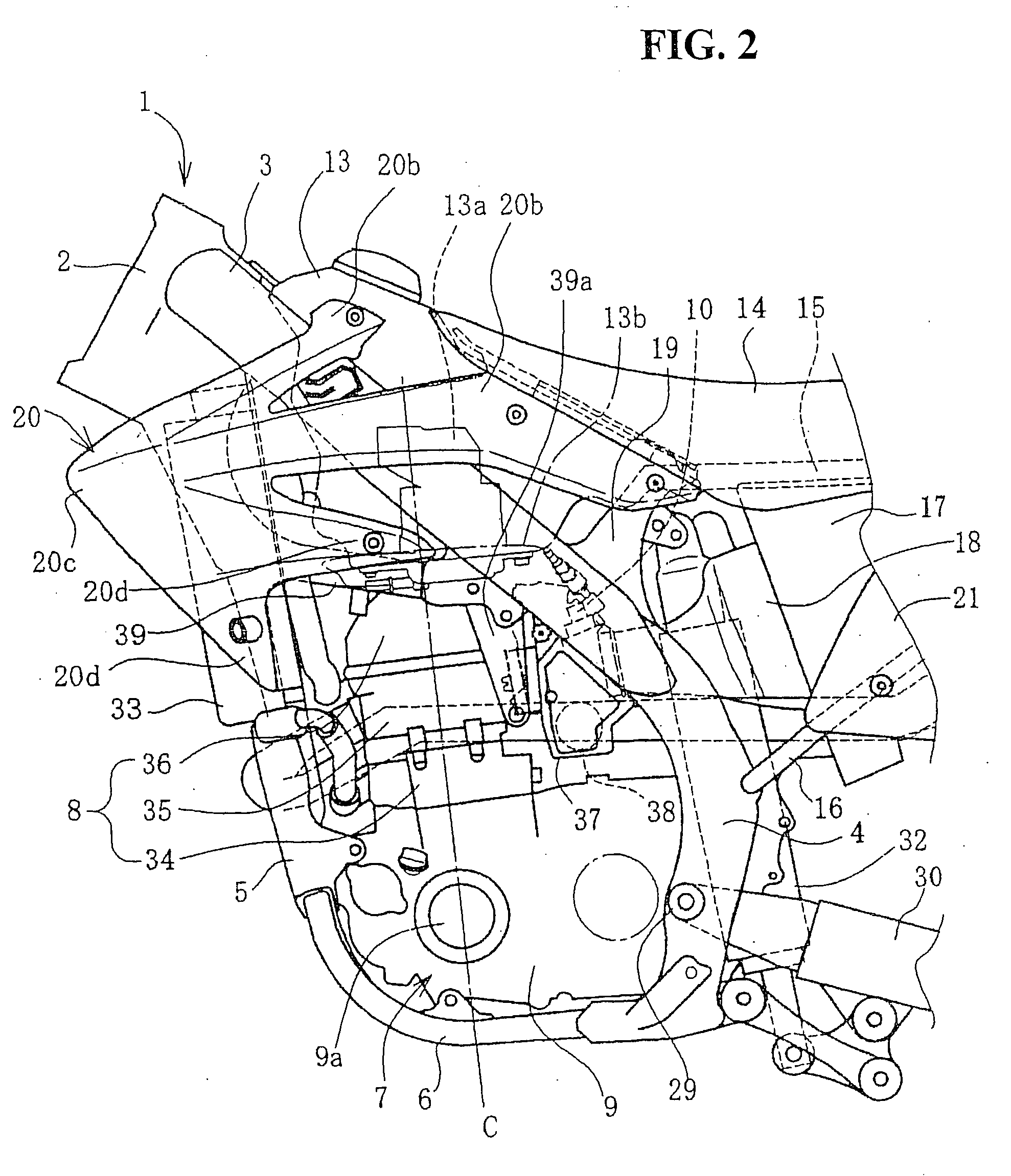
[0033]A specific embodiment to which the present invention is applied will be described below with reference to the accompanying drawings. FIG. 1 is a side elevational view showing an offroad motorcycle, to which the embodiment of the present invention is applied. A vehicle body frame 1 of this motorcycle includes a head pipe 2, a main frame 3, a center frame 4, a down frame 5, and a lower frame 6. Each of these members is connected to each other to form a loop, inside which an engine 7 is supported. Each of the main frame 3, the center frame 4, and the lower frame 6 is provided in pairs of left and right members. The head pipe 2 and the down frame 5 constitute a single member extended along a center of a vehicle body.

[0034]The main frame 3 is extended in a straight line obliquely downwardly toward a rear in a space upward of the engine 7. The main frame 3 is then connected to an upper end portion of the center frame 4 that extends in a vertical direction in a space rearward of the ...


PUM

PropertyMeasurementUnit
elasticaaaaaaaaaa
thickaaaaaaaaaa
shapeaaaaaaaaaa

Abstract

A mounting structure on motorcycle for protecting a capacitor from vibration and heat. In an engine having an upright cylinder a throttle body is connected to an intake path of the cylinder via an insulator, and the throttle body is connected to an air cleaner via a connecting tube. The throttle body is thereby elastically supported relative to the engine and a vehicle body frame via the insulator and the connecting tube. A capacitor is disposed at a position downward of the throttle body. The capacitor is supported integrally with the throttle body using a lower portion of a throttle body cover that covers both left and right sides of the throttle body. A vibration isolating support structure is thus achieved for the capacitor by using the throttle body that is elastically supported.

Description

CROSS-REFERENCE TO RELATED APPLICATION[0001]The present application claims priority under 35 U.S.C. §119 to Japanese Patent Application No. 2006-078318, filed Mar. 22, 2006, the entire contents of which are hereby incorporated by reference.BACKGROUND OF THE INVENTION[0002]1. Field of the Invention[0003]The present invention relates to an electric component mounting structure in motorcycles, or more specifically, vehicles having electronic fuel injection systems.[0004]2. Description of Background Art[0005]A known arrangement, in a motorcycle mounted with an engine having an upright cylinder, makes use of a space rearward of the cylinder and upward of a crankcase to dispose therein capacitors and other electric components, so that the electric components are supported on an upper surface of the crankcase. For example, see Japanese Patent Laid-open No. 2005-219669.[0006]A problem with the known arrangement is that, because the electric components are fixed to the engine, it is necessar...

Claims


Application Information

Patent Timeline
Patent Type & Authority Applications(United States)
IPC IPC(8): F02D11/04F02P3/02B62J99/00B62M7/02F02B61/02F02B77/00F02D9/10F02M35/10F02M35/16
CPCF02M35/10085F02M35/10144F02M35/10249F02P1/086F02M35/10321F02M35/162F02M35/10255
Inventor KONNO, KENJI
Owner HONDA MOTOR CO LTD
Why Eureka
Try Eureka