Gas generating device

a technology of gas generation device and gas generating device, which is applied in the direction of chemistry apparatus and processes, baking ovens, oxygen/ozone/oxide/hydroxide, etc., can solve the problems of difficult to adopt a desirable configuration for use and unavoidable chemical loss

Inactive Publication Date: 2007-09-27
MITSUI BANJO +1
View PDF8 Cites 5 Cited by
  • Summary
  • Abstract
  • Description
  • Claims
  • Application Information

AI Technical Summary

Benefits of technology

[0008] The present invention provides a gas generating device that can initiate the reaction of the liquid-reactive chemical at a specified time, and stop the supply of the reaction liquid at a specified time.
[0051] An agitating-gas-generating material 15 comprising a porous mineral substance is situated on the agitating gas discharge end of the agitating gas supply means, so that the generation of fine gas bubbles is promoted via the gaps in this agitating-gas-generating material 15, thus heightening the agitating effect that the gas bubbles provide.

Problems solved by technology

Accordingly, the resulting chemical loss remains an unavoidable problem.
Accordingly, it is difficult to adopt a desirable configuration for use in which the generation of gas is performed after the personnel-free sealed state has been formed.

Method used


Image

  • Gas generating device
  • Gas generating device
  • Gas generating device

Examples


working examples

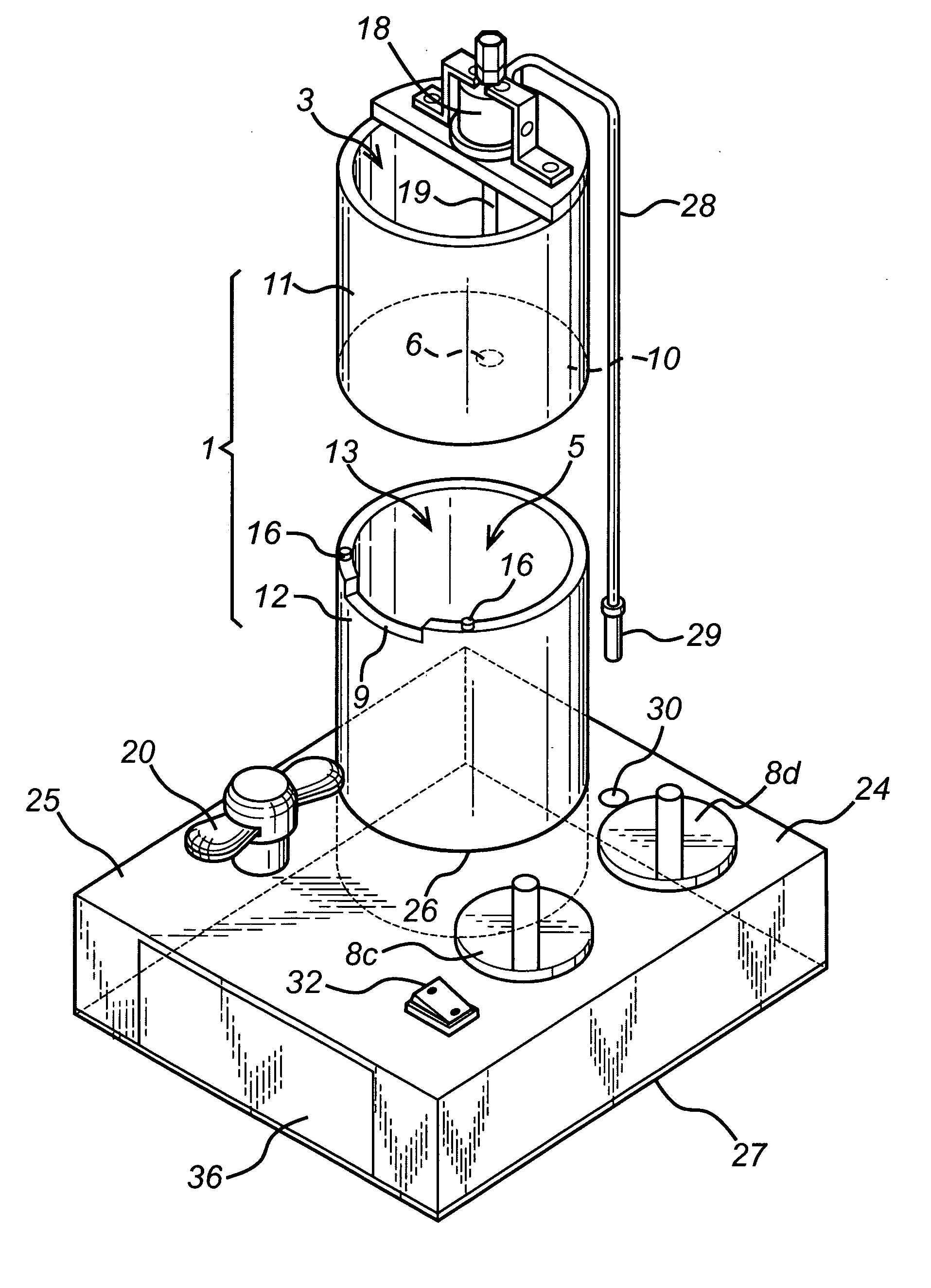
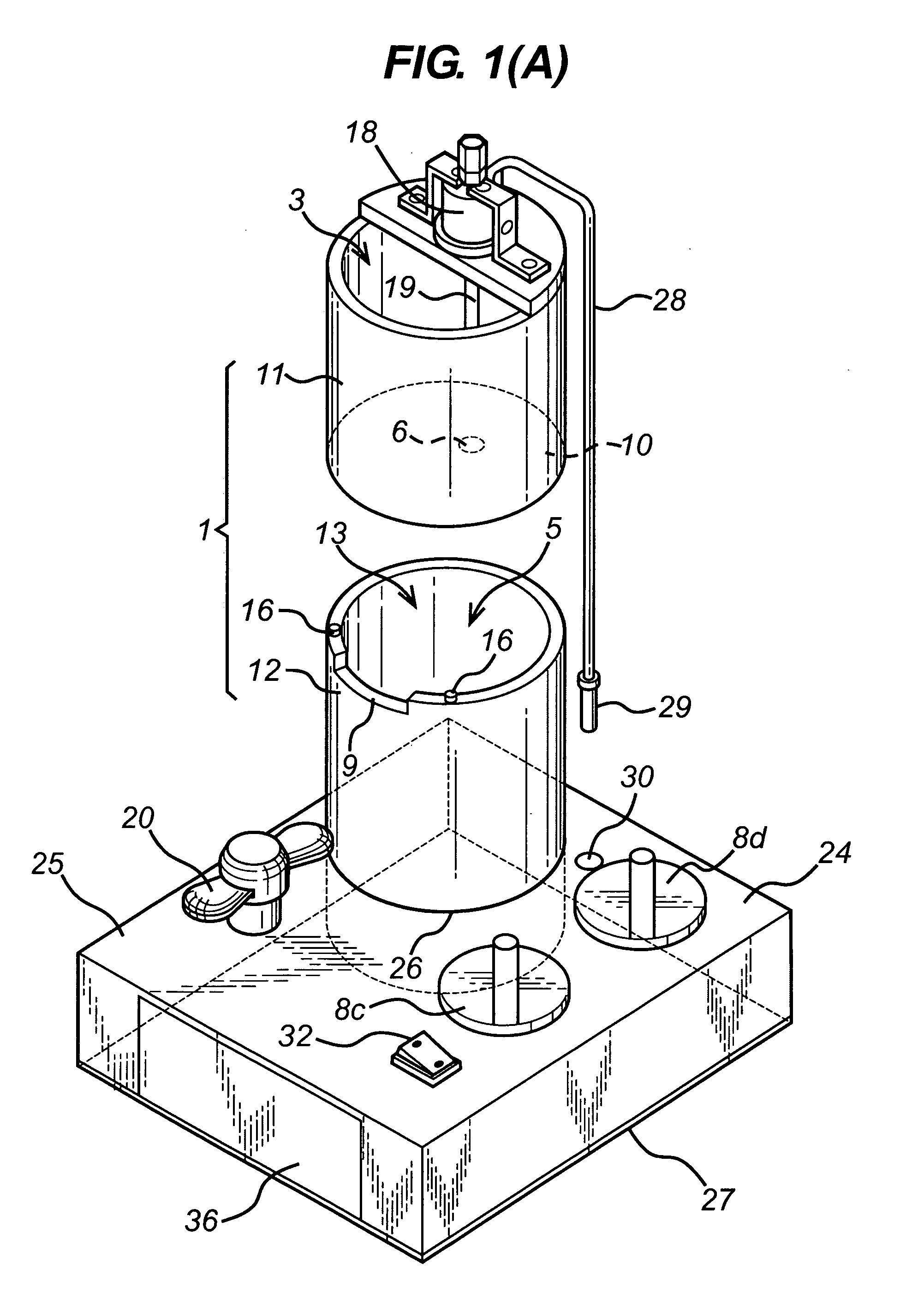
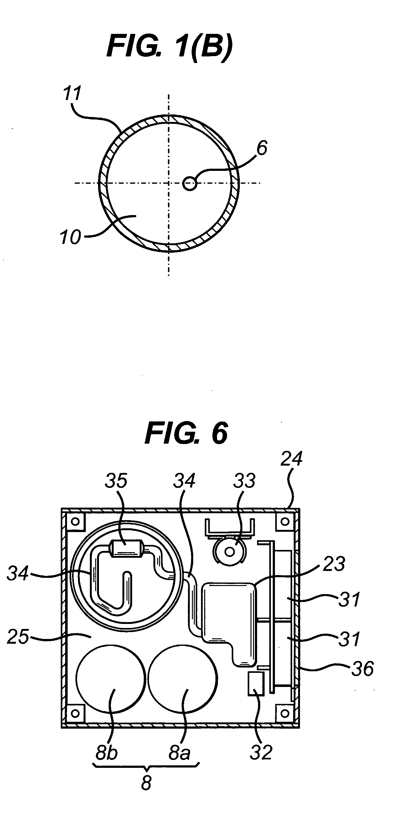
[0022] The best mode for carrying out the present invention shall be described below with reference to FIGS. 1 through 6.

[0023] The gas generating device of the present invention has a structure whereby a liquid-receiving chamber 3 that receives a reaction liquid 2 is formed by an upper tubular part 11 of an upright tubular body 1, and a chemical-receiving chamber 5 which receives a liquid-reactive chemical 4 that generates a gas by reacting with the reaction liquid 2 is formed by a lower tubular part 12 of the tubular body 1. Thus, the reaction liquid 2 and liquid-reactive chemical 4 are separately loaded inside the upper and lower chambers 3 and 5.

[0024] For example, the liquid-reactive chemical 4 is a cyclopropene compound that generates a freshness-preserving gas on reacting with water. Alternative examples of the chemical 4 include peroxidized coal that generates oxygen on reacting with water, manganese dioxide that generates oxygen on reacting with aqueous hydrogen peroxide,...


PUM


Abstract

It is an object of the present invention to provide a gas generating device that can initiate the reaction of a liquid-reactive chemical at a specified time, and stop the supply of the reaction liquid at a specified time, so that generation of a gas by the liquid-reactive chemical can be promoted after workers have finished loading fruits, vegetables, or other produce into a treatment chamber, and a personnel-free sealed state has been formed in the treatment chamber. A gas generating device having an upper tubular part that forms a receiving chamber 3 for a reaction liquid 2 and a lower tubular part that forms a receiving chamber 5 for a liquid-reactive chemical 4, wherein a reaction liquid supply port that supplies the reaction liquid 2 inside the receiving chamber 3 to the receiving chamber 5 is provided between the receiving chambers 3 and 5; and a shut-off valve 7 is provided which opens the supply port 6 and allows the supply of the reaction liquid 2, and closes the supply port 6 and cuts off the supply of the reaction liquid 2. The device further has a gas discharge opening 9 that discharges a gas G generated inside the receiving chamber 5 to the outside from this receiving chamber 5, and further has timer means for setting the supply time of the reaction liquid via the opening and closing of the shut-off valve 7.

Description

[0001] This non-provisional patent application claims priority to prior pending JP Patent Application Number 2005-83894 filed on Mar. 23, 2005. FIELD OF INVENTION [0002] The present invention relates to a gas generating device used to generate a gas by mixing a liquid-reactive chemical and a reaction liquid, e.g., to generate a freshness-preserving gas for fruits, vegetables, and other produce. BACKGROUND INFORMATION [0003] Citation 1 discloses a cyclopropene compound (cyclopropene / cyclodextrin composite) that is effective as a freshness-preserving agent for produce, and further discloses a device for generating a freshness-preserving gas (cyclopropene gas) by reacting this cyclopropene compound with water. [0004] The above-mentioned cyclopropene gas generating device has a structure in which a reaction liquid (water) and cyclopropene compound are introduced together into the same tube via a top opening of an upright tubular body; air or nitrogen, and carbon dioxide, are introduced ...

Claims


Application Information

Patent Timeline
Patent Type & Authority Applications(United States)
IPC IPC(8): A21B1/08
CPCA01N3/00A23B7/144B01J7/02Y02E60/36C01B13/0211C01B13/0225C01B3/08
Inventor MITSUI, BANJOMAKIHARA, DAIZABURO
Owner MITSUI BANJO
Why Eureka
Try Eureka