Storage rack column protector

a column protector and storage rack technology, applied in the field of storage rack column protectors, can solve the problems of affecting the appearance of the column protector, the amount of steel in the sleeve which is shaped, and the damage to the column protector, etc., and achieves the effect of reducing the cost of production, and reducing the amount of steel in the sleev

Inactive Publication Date: 2007-09-27
EQUIP BONI
View PDF16 Cites 15 Cited by
  • Summary
  • Abstract
  • Description
  • Claims
  • Application Information

AI Technical Summary

Benefits of technology

[0008] An advantage of the present invention is that the storage rack column protector is of simplified form and thus of less expense when compared to earlier proposals.
[0009] Another advantage of the present invention is that the storage rack column protector efficiently absorbs any impact without damaging the impacting object.
[0010] A further advantage of the present invention is that the storage rack column protector provides for an additional anchor fastener while protecting the same.
[0011] Yet another advantage of the present invention is that the storage rack column protector can be used as a dynamic stopper and / or guiding device, to ensure proper positioning of the fork lift relative to the rack, along the column; and similarly in between two adjacent columns of a same rack when used independently of the column.
[0012] Another advantage of the present invention is that the storage rack column protector allows space savings on the storage racks by forcing the wheels disposed at the front of a fork lift to align therewith, and voluntarily slightly bump there against.

Problems solved by technology

When the hit occurs at an angle, the column may be subject to twisting about the anchor axis, thus damaging the column and most likely some other nearby sections of the storage rack.
This column protector would be relatively expensive to produce in terms of bonding the elastomeric flange and the cushions to the sleeve.
Furthermore, the amount of steel in the sleeve which is shaped, would be costly thereby compounding the overall price of the racking.
A number of bolts are necessary to secure the foot to the floor and the very shape of the collar and the foot requires expensive casting.
The prior art outlined supra presents examples of column protector of some complexity and thus of high cost thereby adding to the overall cost of the racking system.
Moreover, maintenance or replacement of the various elements comprising the column protectors would be of high cost and thus disadvantageous.

Method used


Image

  • Storage rack column protector
  • Storage rack column protector
  • Storage rack column protector

Examples


Embodiment Construction

[0032] With reference to the annexed drawings the preferred embodiments of the present invention will be herein described for indicative purpose and by no means as of limitation.

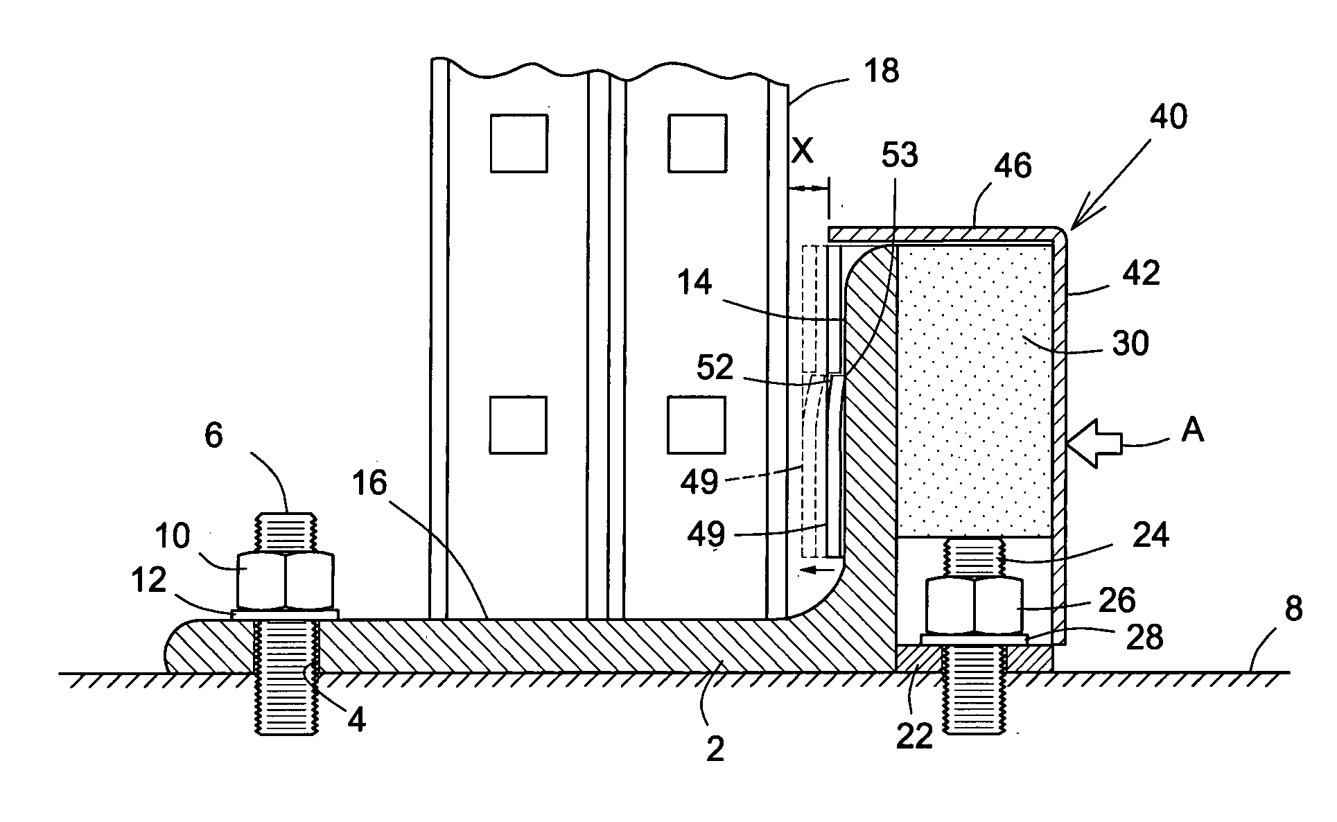
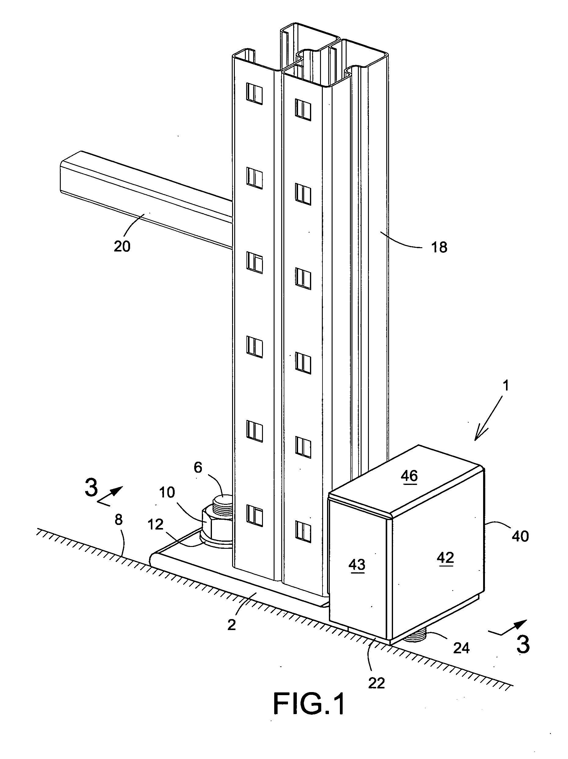
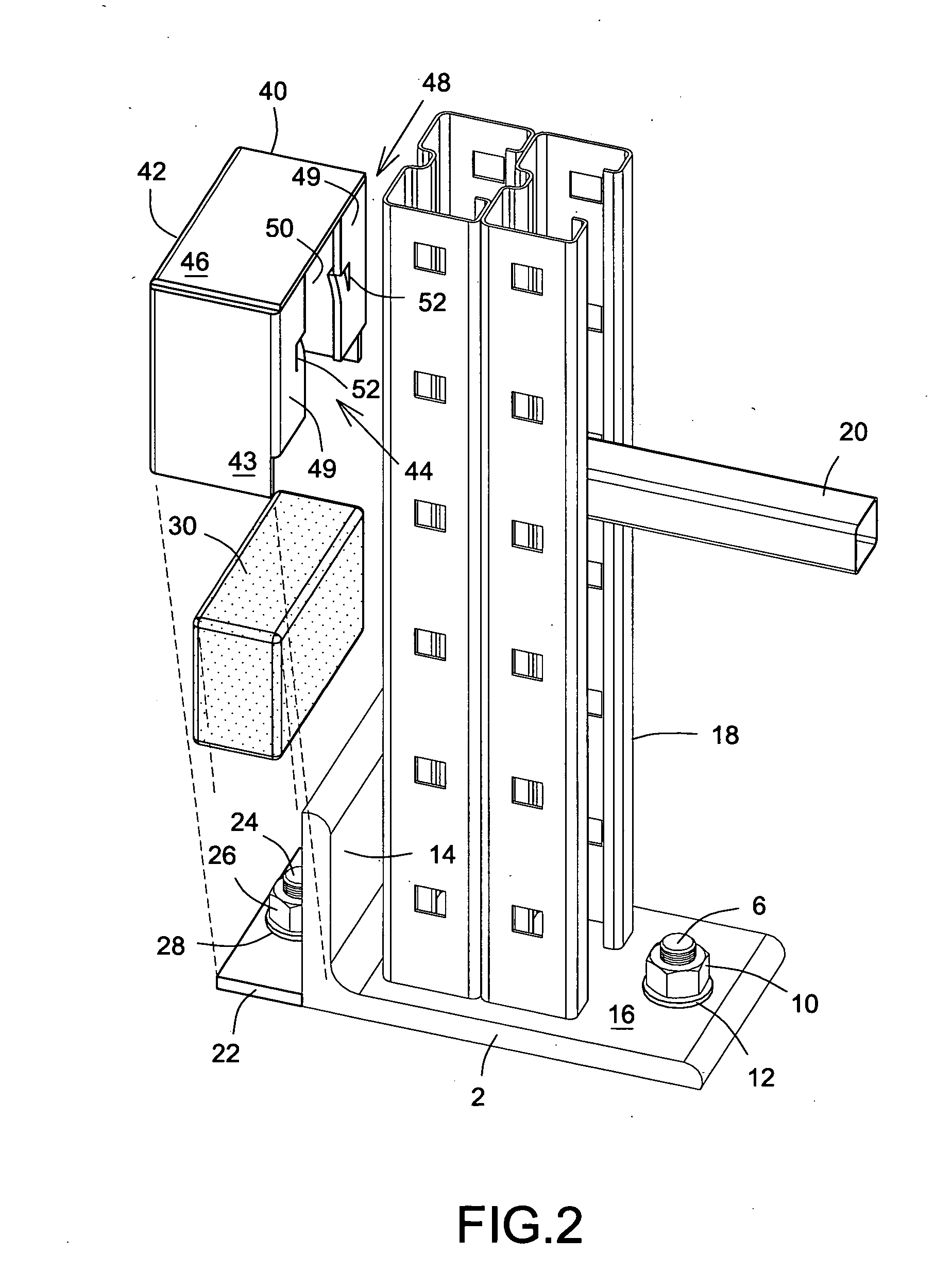
[0033] A storage rack column protector is shown generally at 1 and comprises a base plate 2 provided with a through hole 4 for an anchorage bolt 6 extending into a floor 8 and being secured in use by a nut 10 and a washer 12. Upstanding at one end of the base plate 2 is a flange 14 and defined between the flange and the bolt hole is a column support region 16, a column being shown at 18 for illustrative purposes duly supported on said region 16. A rack cross beam is shown in part at 20.

[0034] On the other side of the flange 14 remote from the column support region 16 is another plate 22 shown secured to the floor 8 in similar fashion to the base plate 2 with an anchor bolt 24 with a nut 26 and a washer 28, the plate 22 being disposed closely adjacent to the flange 14 and typically secured thereto by weldin...


PUM


Abstract

A storage rack column protector includes a base plate securable to the floor and with an upstanding flange at one end thereof, the base plate providing a support surface on which the column sits in use. A buffer housing incorporating a resilient block is disposed on the side of the flange remote from the column, the housing embracing the flange. In the event of impact the buffer housing and the resilient block move to absorb the shock and thus protect the column from damage.

Description

FIELD OF THE INVENTION [0001] The present invention relates to a storage rack column protector for the foot of a rack column in warehouse racking systems in order to prevent or minimize damage to the column in the event of impact, for example by a fork lift. BACKGROUND OF THE INVENTION [0002] It is well known in the art to position such a protector around or at the foot of a support column in a storage racking system since the occurrence of accidental impact is not uncommon from the wheels disposed at the front of a fork lift. The usage of pallets facilitates the compact storage of goods in large volumes with relative ease of access, but the placement thereof on the racking demands reasonably accurate maneuvering of the fork lift: in the first instance to align the load with the selected rack, to elevate the same to the appropriate level and then to advance the fork lift to deliver and set down the load safely onto the rack at the correct distance from the front of the rack. It is a...

Claims


Application Information

Patent Timeline
Patent Type & Authority Applications(United States)
IPC IPC(8): A47B57/00
CPCA47B91/00B65G1/02Y10T428/24008Y10T16/95B65G2207/40
Inventor RIOUX, SYLVAIN
Owner EQUIP BONI
Why Eureka
Try Eureka