Expandable finger gripper

a finger gripper and expandable technology, applied in the field of pneumatically controlled expandable grippers, can solve the problems of reducing the use efficiency of the tool, and destroying the finger gripper, so as to achieve the effect of reducing the weight of the tool

Active Publication Date: 2007-09-27
GIMATIC SRL
View PDF9 Cites 30 Cited by
  • Summary
  • Abstract
  • Description
  • Claims
  • Application Information

AI Technical Summary

Benefits of technology

[0006]Advantageously, thanks to this type of configuration, the finger gripper is much simpler, lighter and less costly also due to the fact that it has a flexible and expandable gripper component and not an inflatable one. This gripper element can now be much thicker, consequently more robust, have greater wear resistance, and have a longer and more efficient life span. Above all it can be easily replaced without having to substitute or eliminate any other component of the tool. Where required, the flexible element of the gripper can also be provided with a profiled surface, such as for example corrugated, so as to offer not one but several grip areas.
[0007]Furthermore, the tool is able to function using even very considerable pressure levels, in any case not limited, in order to be able to develop even higher forces in that the flexible gripper element is neither filled or directly subjected to the thrust of air under pressure so that there is no risk of it exploding. This also means there is no need for a pressure regulator, also costly, on board the tool, as is, on the other hand, required in the abovementioned finger gripper whose technique is well known.

Problems solved by technology

Such a finger however has some drawbacks which the technicians in the sector are well aware of.
The working pressure must be in proportion to the thickness of the walls of the inflatable element and if not limited to its maximum value could cause the element to explode and subsequently the breakdown of the finger gripper.
Consequently, to avoid this possibility each inflatable finger must also be equipped with a pressure adjustor, thus further increasing the weight of the tool, it being already cumbersome in that it has a solid and heavy body.
Furthermore, when worn or broken, the inflatable gripper cannot be replaced so this means that the whole finger must be discarded.

Method used


Image

  • Expandable finger gripper
  • Expandable finger gripper
  • Expandable finger gripper

Examples


Embodiment Construction

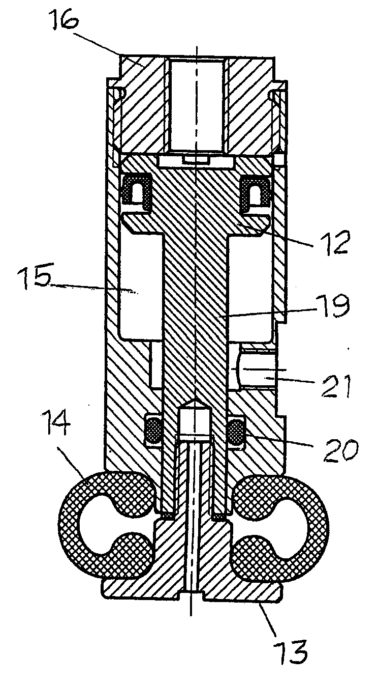
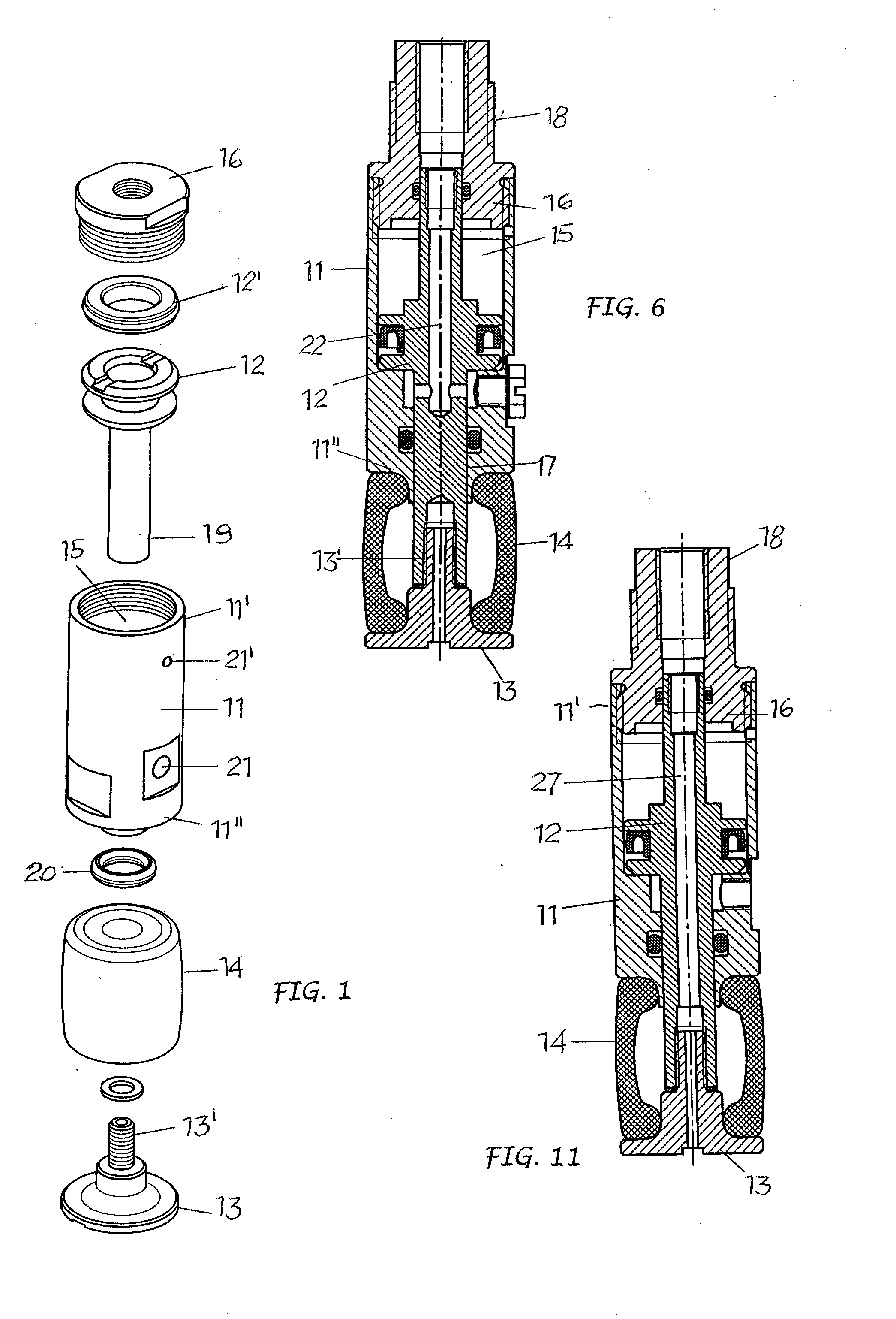
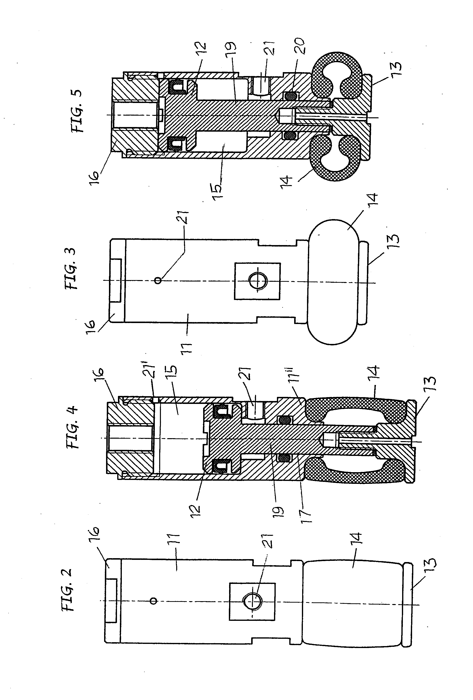
[0018]As shown, the finger gripper proposed here basically comprises, a supporting body 11, a pneumatic control piston 12, a compression disk 13 and an expandable gripper element 14.

[0019]The supporting body 11, that can be cylindrical, has a proximal end 11′ and a distal end 11″ and forms internally a chamber 15 closed by a plug 16 on the proximal end and having an end bore 17 on the distal end. At its proximal end, the supporting body 11, or even its plug 16, has a connection or fitting 18—FIGS. 6, 11—to connect the finger gripper to a manipulator—not shown.

[0020]The control piston 12 is seal housed with a relative seal 12′ and moving is said chamber 15. It has a rod 19, which extends into the end bore 17 with the interposition of a seal 20 and which protrudes from the distal end of said body. The compression disk 13 is connected to the end of the rod 19 of the piston 12 by means of, for example, a threaded shank 13′.

[0021]The expandable gripper element 14 is basically tubular and...


PUM


Abstract

The invention concerns a pneumatically controlled finger gripper that comprises a supporting body (11) with a proximal and a distal end, a pneumatic control piston (12) guided and moving alternatively in said body, a compression disk (13) connected to, and moving axially with, said piston relatively at the distal end of said supporting body, and a flexible gripper element (14) assembled between said compression disk (13) and said distal end of the supporting body (11) and moving between a contracted and expanded position in response to the movements of the control piston with the compression disk between an inactive and active position.

Description

FIELD OF THE INVENTION[0001]This invention concerns in general means for gripping items, objects or containers, and refers in particular to a pneumatically controlled expandable gripperSTATE OF THE TECHNIQUE[0002]Among the means for gripping and handling items while carrying out their production processes and / or when being used, an inflatable finger gripper is already well known. It comprises an almost tubular gripper element, made of an elastomer material such as silicone, bent to form two concentric walls, the edges of which are linked, by means of tightening rings, to the supporting body so as to form an annular chamber. The gripping element is usually in a contracted position; as such it can be inserted into the cavity of the body to be picked up, after which air under pressure is blown into the chamber, through a passage provided in the body support, to swell the element and expand it so that it grips the item.[0003]Such a finger however has some drawbacks which the technicians...

Claims


Application Information

Patent Timeline
Patent Type & Authority Applications(United States)
IPC IPC(8): B66C1/54
CPCB25J15/12Y10T279/1066B66C1/54B65G47/908B25J15/0047
Inventor MAFFEIS, GIUSEPPE
Owner GIMATIC SRL
Why Eureka
Try Eureka