Underfrequency Load Shedding Protection System

a load shedding protection and frequency protection technology, applied in the direction of power network operation system integration, dc source parallel operation, ac network voltage adjustment, etc., can solve the problem of power system frequency not recovering to within a predetermined allowable range, and achieve the effect of stably managing the power system

Inactive Publication Date: 2007-09-27
THE TOKYO ELECTRIC POWER CO INC
View PDF1 Cites 56 Cited by
  • Summary
  • Abstract
  • Description
  • Claims
  • Application Information

AI Technical Summary

Benefits of technology

[0008] An underfrequency load shedding protection system of the present invention is one for stably managing a power system by recovering the power system frequency to within a predetermined range when the power system frequency drops, characterized by comprising an underfrequency level detection unit for judging an underfrequency level of the power system frequency when the power system frequency drops resulting

Problems solved by technology

However, there may be a case where the power system frequency does not recover

Method used


Image

  • Underfrequency Load Shedding Protection System
  • Underfrequency Load Shedding Protection System
  • Underfrequency Load Shedding Protection System

Examples


first embodiment

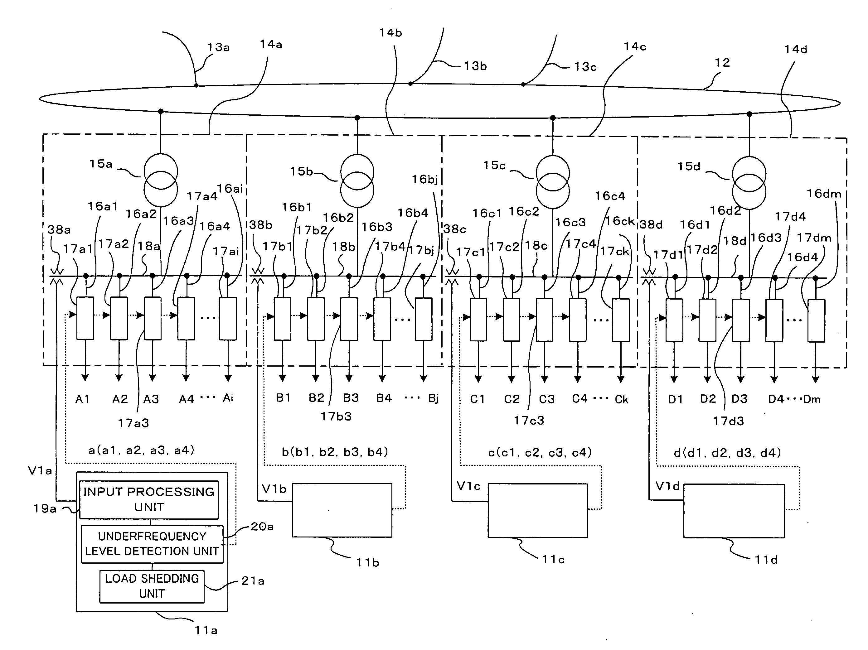
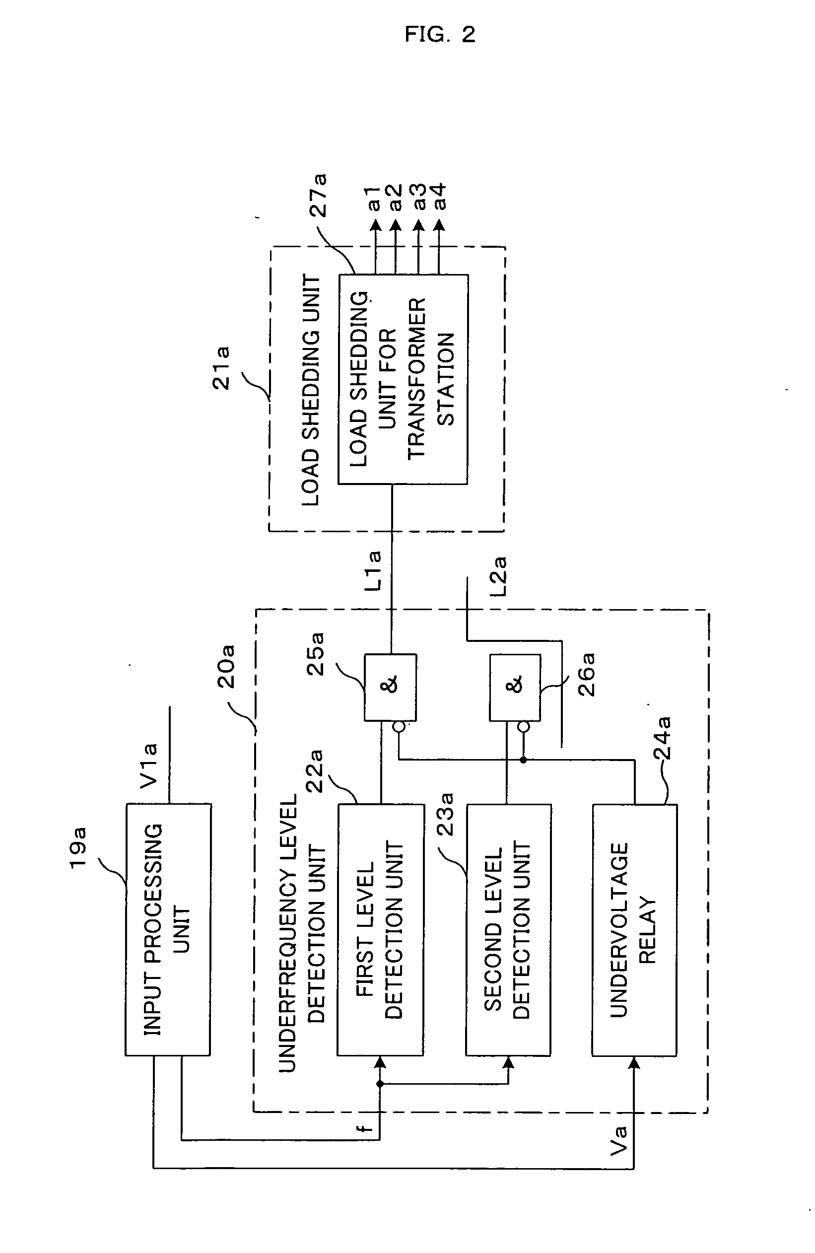
[0029]FIG. 2 is a block configuration diagram of the underfrequency load shedding protection system 11a according to the present invention. The input processing unit 19a receives the voltage V1a detected by the voltage transformer 38a and obtains a frequency f of the voltage V1a and at the same time, obtains a voltage value Va and outputs it to the underfrequency level detection unit 20a.

[0030] The underfrequency level detection unit 20a comprises:

[0031] a first level detection unit 22a that judges whether or not the power system frequency f is within a first level range and outputs the logical value “1” when it is within the first level range;

[0032] a second level detection unit 23a that judges whether or not the power system frequency f is within a second level range and outputs the logical value “1” when it is within the second level range;

[0033] an undervoltage relay 24a that outputs the logical value “1” when the voltage value Va of the voltage V1a is equal to or less than ...

second embodiment

[0076] Next, FIG. 9 is a circuit configuration diagram of the load shedding unit for the transformer station A 27a of the load shedding unit 21a in the The load shedding unit for the transformer station A 27a comprises the timers T1 to T8 each having a predetermined time and the OR circuits OR1 to OR4 for calculating a logical OR of a combination of two outputs of the timers T1 to T8 and the detection signals for rate of change of frequency Ma (0.4), Ma (0.5), Ma (1.0), and Ma (2.0). The timers T1 to T8 and the OR circuits OR1 to OR4 realize assignment of the load shedding commands a1 to a4 to the loads, which are the candidates for load shedding shown in FIG. 8.

[0077] For example, when the logical value “1” is input by any one of the output signals from the timers T1 and T2, Ma (0.4), Ma (0.5), Ma (1.0), and Ma (2.0), the load shedding command al from the OR circuit OR1 is output to the circuit breaker 17a1 and the load A1 is shed. Similarly, when the logical value “1” is input by...

third embodiment

[0082] The rate of change of frequency detection unit 31a in the third embodiment comprises two predetermined ranges (a first predetermined range and a second predetermined range) as a predetermined range equal to or less than the predetermined value of the power system frequency. The first rate of change of frequency detection unit 35a comprises the first predetermined range and the second rate of change of frequency detection unit 36a comprises the second predetermined range. Then, the first rate of change of frequency detection unit 35a judges the rate of change of the power system frequency within the first predetermined range and the second rate of change of frequency detection unit 36a judges the rate of change of the power system frequency within the second predetermined range.

[0083] The first rate of change of frequency detection unit 35a measures the time taken by the received power system frequency f to drop through the first predetermined range and if the time is equal to...


PUM


Abstract

An underfrequency load shedding protection system for stably managing a power system by recovering a power system frequency to within a predetermined range when the power system frequency drops. An underfrequency level detection unit judges an underfrequency level of the power system frequency when the power system frequency drops resulting from power generation shortage in the power system and a load shedding unit sequentially sheds loads determined in advance based on a staying time when the power system frequency stays at any one of the underfrequency levels judged by the underfrequency level detection unit and sheds on this occasion more loads quickly when the underfrequency level at which the power system frequency stays is large.

Description

TECHNICAL FIELD [0001] The present invention relates to an underfrequency load shedding protection system for stably managing a power system by recovering a power system frequency to within a predetermined range when the power system frequency drops. BACKGROUND ART [0002] In general, a plurality of generators is connected to a power system and power generated by a generator is supplied to a load via a power transmission line. The power system voltage is managed so as to fall within a predetermined range depending on each of the voltage classes of the power transmission line and the power system frequency is also managed so as to fall within a predetermined range. A generator connected to the power system is operated in synchronization with the power system frequency so that the terminal voltage becomes a predetermined voltage. [0003] In such a power system, when loads increase or decrease, the power system voltage and the power system frequency change, therefore, the power system vo...

Claims


Application Information

Patent Timeline
IPC IPC(8): H02J3/14H02J3/24
CPCH02J3/14Y04S20/222Y02B70/3225H02H3/033H02H3/46H02J2310/12
Inventor TSUKIDA, JIROUYASUDA, TADAAKIIMAI, SHINICHI
Owner THE TOKYO ELECTRIC POWER CO INC
Why Eureka
Try Eureka