Method for manufacturing a RFID electronic tag

a technology of electronic tags and tags, applied in the direction of burglar alarms by hand-portable objects removal, burglar alarm mechanical actuation, etc., can solve the problems of high cost and inability to choose low-cost antennas integrated into packaging foils, and achieve the effect of low cost and attractiveness of ready-to-fit tags

Active Publication Date: 2007-09-27
STMICROELECTRONICS SRL
View PDF5 Cites 13 Cited by
  • Summary
  • Abstract
  • Description
  • Claims
  • Application Information

AI Technical Summary

Benefits of technology

[0020] The technique disclosed in the '166 patent to produce the conductors for detecting the opening of the cells of the blister requires providing two layers of insulating material to prevent the top aluminum layer of the packaging foil of the blister from short-circuiting the network of conductors. This technique is expensive and cannot be chosen to produce a low-cost antenna integrated into a packaging foil. The cost of the ready-to-fit tags thus remain more attractive.
[0021] An object of the present invention is to provide a method enabling an electronic tag to be produced at low cost that can optionally be destroyed when the packaging enclosing the tag is opened.

Problems solved by technology

This technique is expensive and cannot be chosen to produce a low-cost antenna integrated into a packaging foil.

Method used


Image

  • Method for manufacturing a RFID electronic tag
  • Method for manufacturing a RFID electronic tag
  • Method for manufacturing a RFID electronic tag

Examples


Embodiment Construction

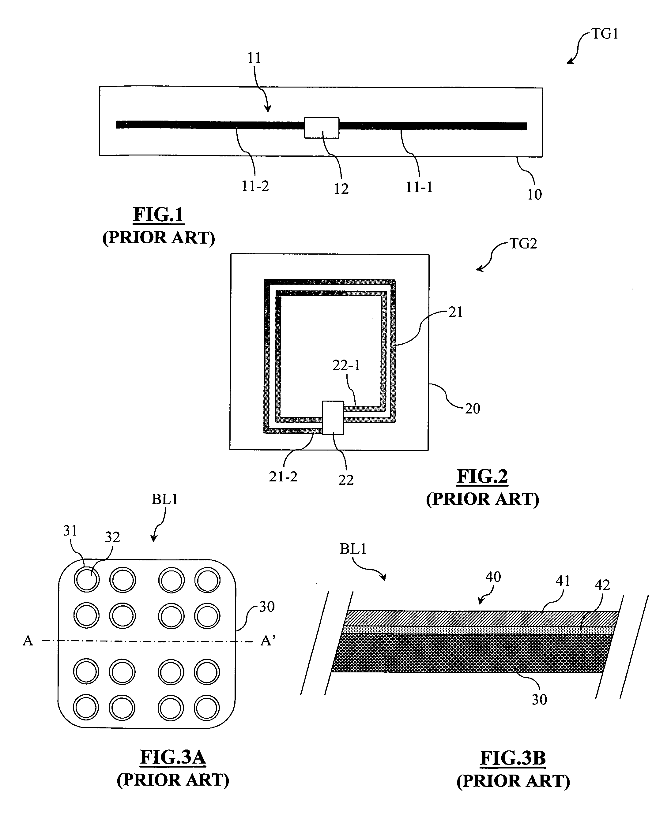
[0082] As indicated above, the present invention is based on the straightforward principle that the aluminum film of the packaging foils, particularly those used to cover the blisters, can be used to form an RF or UHF antenna by removing metal material from appropriate areas so as to provide an antenna pattern.

[0083]FIG. 3A represents a classic blister BL1 viewed from above before being closed. At this stage, the blister is a thermoformed strip 30 comprising cells 31 receiving tablets 32. After insertion of the tablets 32, the strip is closed by a foil with metal film that will be designated as a “packaging foil.” The present invention does not draw a difference between the packaging foils used to fully pack a product and the packaging foils applied to one side or one part of a product to close it.

[0084] The packaging foil is represented in cross-section in FIG. 3B, along a cross-sectional axis AA′ represented in FIG. 3A, and is designated by the reference 40. It comprises an alum...


PUM


Abstract

A method for manufacturing an electronic tag to be affixed onto a product includes providing, in an electrically conductive film of a foil for packaging, packing or transporting the product, areas devoid of any electrically conductive material for delimiting in the electrically conductive film at least one antenna pattern for forming an antenna for an RFID tag. A semiconductor chip is connected to the antenna for forming an electronic tag.

Description

FIELD OF THE INVENTION [0001] The present invention relates to the production of RFID (Radio Frequency Identification) electronic tags. BACKGROUND OF THE INVENTION [0002] RFID electronic tags are produced by passive contactless integrated circuits, or transponders, which can be of the electrical coupling-type or the inductive coupling-type. [0003] Electrical coupling contactless integrated circuits, or UHF contactless integrated circuits, are electrically powered by a UHF electric field oscillating at several hundred MHz. They send data by modulating the reflection rate of their antenna circuit (a technique called backscattering). Such integrated circuits are, for example, described by the industrial specification EPCTM-GEN2 (Radio-Frequency Identity Protocols Class-1 Generation-2—UHF RFID Protocol for Communications at 860 MHz-960 MHz), which is in the process of being standardized. They are generally used in so-called long range applications, in which the distance between the inte...

Claims


Application Information

Patent Timeline
Patent Type & Authority Applications(United States)
IPC IPC(8): G08B13/14
CPCG06K19/07718G06K19/07749G06K19/07758H01L2224/16H01L2924/10253H01L2924/3011H01L2924/00
Inventor FIDELIS, SYLVAINRIZZO, PIERRE
Owner STMICROELECTRONICS SRL
Why Eureka
Try Eureka