Display apparatus, burn-in correction system and burn-in correction method

Inactive Publication Date: 2007-09-27
FUNAI ELECTRIC CO LTD
View PDF6 Cites 7 Cited by
  • Summary
  • Abstract
  • Description
  • Claims
  • Application Information

AI Technical Summary

Benefits of technology

[0026] According to the third aspect of the invention, the burn-in correction method includes the steps of: lighting each pixel constituting the display panel in order under the preset lighting condition; acquiring the imaged image data by imaging each lighted pixel from viewing side with the imaging apparatus; and correcting the luminance of each pix

Problems solved by technology

If the burn-in occurs, the light emission state of the burn-in place has changed to make it impossible to perform an adequate display.
However, according to the techniques disclosed in Patent Document 1 and Patent Document 2, it is possible to correct color deterioration and the like, but, because both of the techniques correct the parts where color unevenness has occurred by imaging the whole screen with a video camera or the like

Method used


Image

  • Display apparatus, burn-in correction system and burn-in correction method
  • Display apparatus, burn-in correction system and burn-in correction method
  • Display apparatus, burn-in correction system and burn-in correction method

Examples


Example

[0034] In the following, an embodiment of the present invention will be described in detail, referring to the attached drawings.

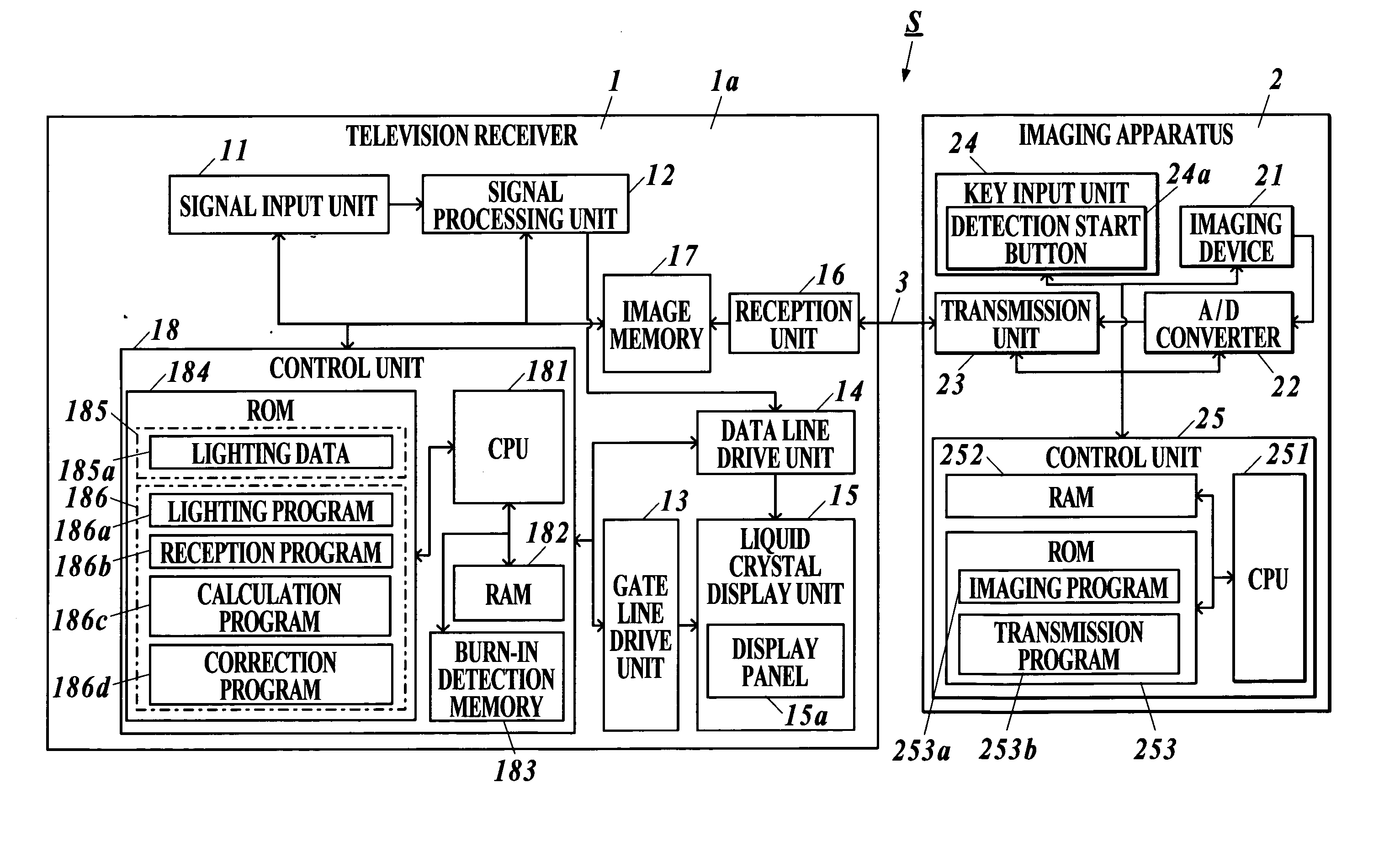
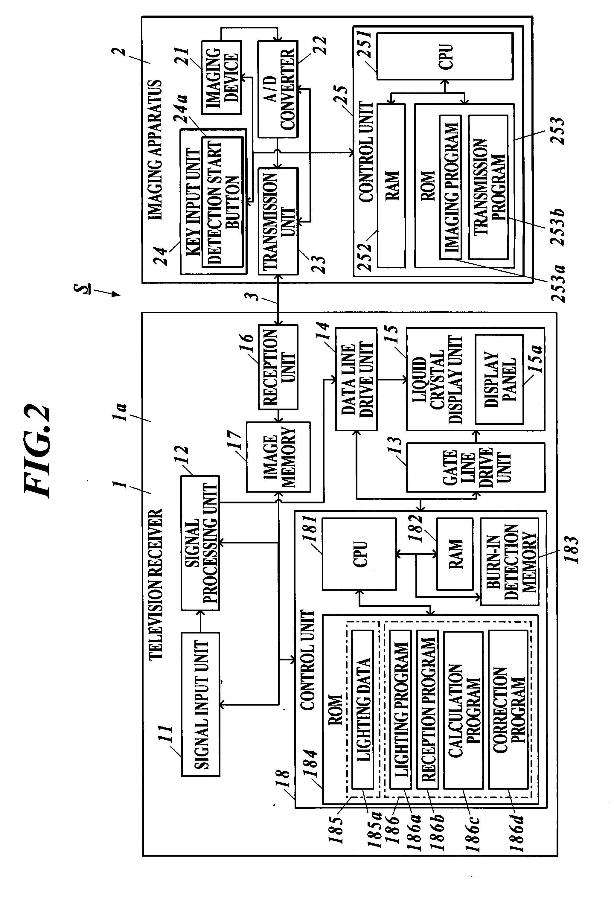
[0035] Incidentally, FIG. 1 is a block diagram illustrating a burn-in correction system S of the present embodiment. FIG. 2 is a block diagram showing the configuration of the principal parts of a television receiver 1 and an imaging apparatus 2 that constitute the burn-in correction system S of the present embodiment. FIG. 3 is a sectional view of a liquid crystal display unit 15 provided in the television receiver 1. Moreover, FIG. 4 is a plan view of a glass substrate 151 in the liquid crystal display unit 15.

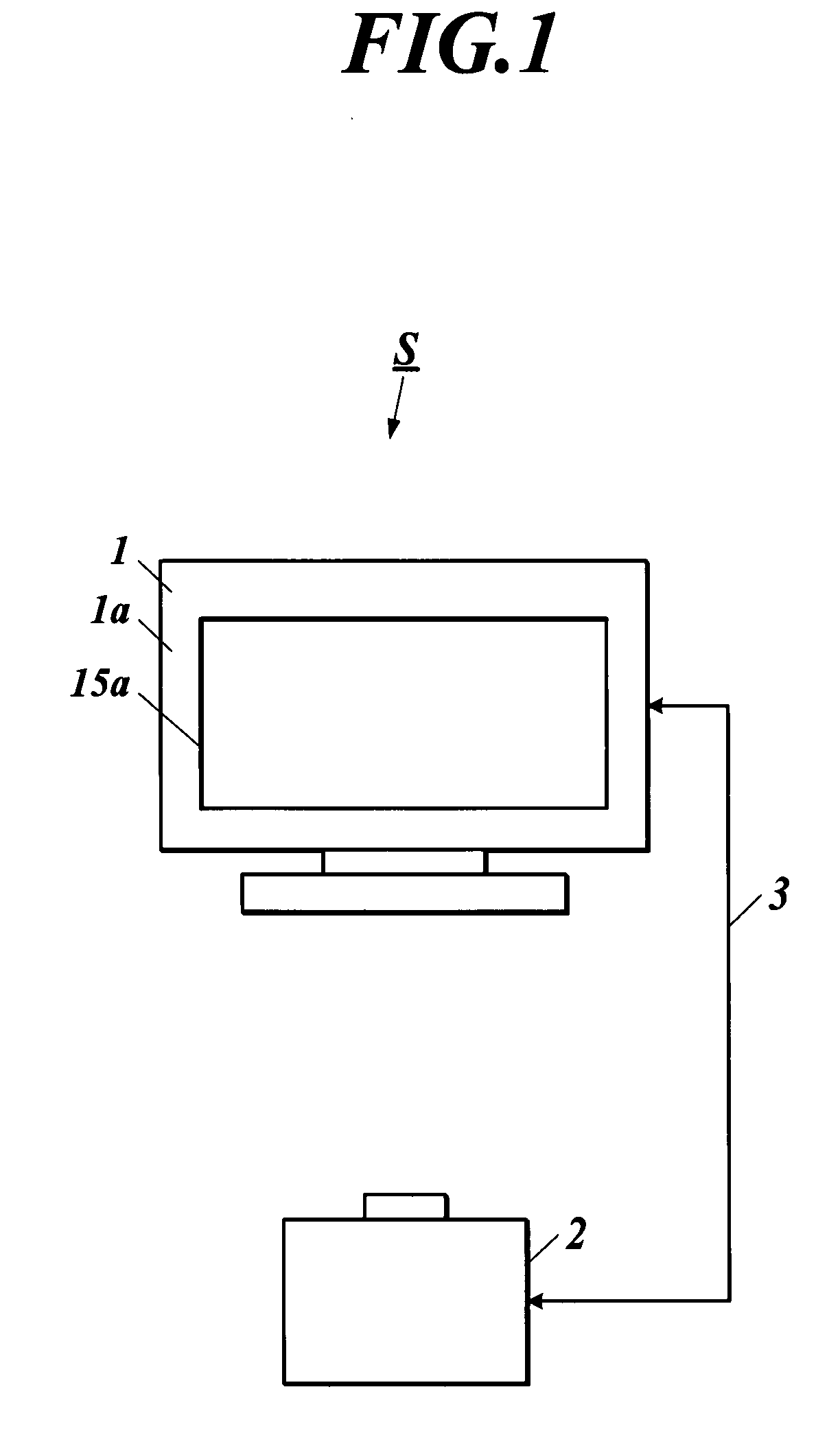
[0036] As shown in FIG. 1, the present burn-in correction system S includes the television receiver 1 as a display means and a display apparatus and the imaging apparatus 2 as an imaging means, which are connected with each other through a communication line 3. The communication line 3 is a wireless communication line using an IR signal or the lik...


PUM


Abstract

A burn-in correction system including a display unit equipped with a display panel displaying an image according to input image data, and an imaging unit acquiring imaged image data by imaging the display panel from a viewing side, the system correcting burn-in on the display panel. The system further includes: a lighting unit lighting each pixel constituting the display panel in order under a preset lighting condition; a calculation unit calculating a difference value between luminance of the imaged image data of each pixel lighted by the lighting unit, the imaged image data acquired by imaging each lighted pixel with the imaging unit, and luminance preset in the lighting condition; and a correction unit correcting luminance of each pixel based on the input image data, the correcting performed based on the difference value calculated by the calculation unit.

Description

BACKGROUND OF THE INVENTION [0001] 1. Field of the Invention [0002] The present invention relates to a display apparatus equipped with a burn-in correction function, a burn-in correction system and a burn-in correction method. [0003] 2. Related Art [0004] The phenomenon called as burn-in sometimes occurs in a display apparatus equipped with a display panel such as a liquid crystal display (LCD) and a plasma display panel (PDP). The burn-in is the phenomenon in which the trace of a pattern remains on a display screen when the same image has been displayed over a long time, or when the cumulative display time of the same image becomes a long time. If the burn-in occurs, the light emission state of the burn-in place has changed to make it impossible to perform an adequate display. Accordingly, various techniques have been conventionally proposed for settling the burn-in phenomenon. [0005] For example, Patent Document 1 discloses a projector which is equipped with a color unevenness cor...

Claims


Application Information

Patent Timeline
IPC IPC(8): H04N3/20G02F1/133G09G3/20G09G3/36H04N5/66
CPCG02F1/1309G09G3/3611G09G2320/0233G09G2360/147G09G2320/046G09G2320/0693G09G2320/043
Inventor KATAYAMA, TAKAHIROTAKAGI, TOSHIHIRO
Owner FUNAI ELECTRIC CO LTD
Why Eureka
Try Eureka