Supercharge Your Innovation With Domain-Expert AI Agents!

Apparatus and method for detection of optical systems in a terrain area

Inactive Publication Date: 2007-09-27
CARL ZEISS OPTRONICS
View PDF5 Cites 5 Cited by
  • Summary
  • Abstract
  • Description
  • Claims
  • Application Information

AI Technical Summary

Benefits of technology

[0010] The measures according to the invention provide an autonomous apparatus and scanning unit for detection of optical systems in a terrain area, in a simple and advantageous manner. This scanning unit can make the determined position data of a recorded optical system available via an interface to further appliances or display apparatuses or cameras, by which means the position can be superimposed directly on an image of the terrain area on a display apparatus which receives the position data from the interface. In this case, information relating at least to the intensity and the elevation of the recorded retroreflected laser radiation is transmitted. A scan position sensor is provided for this purpose. The use of a laser arrangement makes it possible to scan the terrain area to be checked for the presence of optical systems with little energy being consumed, since all that is necessary is to pass a laser beam in the form of a dot over the terrain area.
[0017] This measure has the advantage that the relatively small elevation range that is required for the present purposes, for example of 6° to 10°, can be scanned through in a simple manner.
[0018] It is advantageous for the oscillation axis of the oscillating mirror to be a horizontal axis, in particular when the apparatus is in the in-use position, and to have the capability for the apparatus to be scanned horizontally, in particular through 360°, in the in-use position.
[0019] This allows the terrain area to be scanned to be checked quickly and easily via the operator of the system and / or of the apparatus, for example, manually carrying out an appropriate horizontal scan. Alternatively or additionally, the apparatus can be combined with an automatic scanning device, which can scan horizontally through 360°. In one advantageous refinement of the method according to the invention, the laser arrangement, the scan position sensor and the display apparatus for scanning of the terrain area can then be scanned synchronously in an appropriate manner on a horizontal plane.

Problems solved by technology

Visual light is generally not used for illumination since, on the one hand, eye safety with laser light in the visual band is not ensured and, on the other hand, the visual light can itself be easily detected.

Method used


Image

  • Apparatus and method for detection of optical systems in a terrain area
  • Apparatus and method for detection of optical systems in a terrain area

Examples


Embodiment Construction

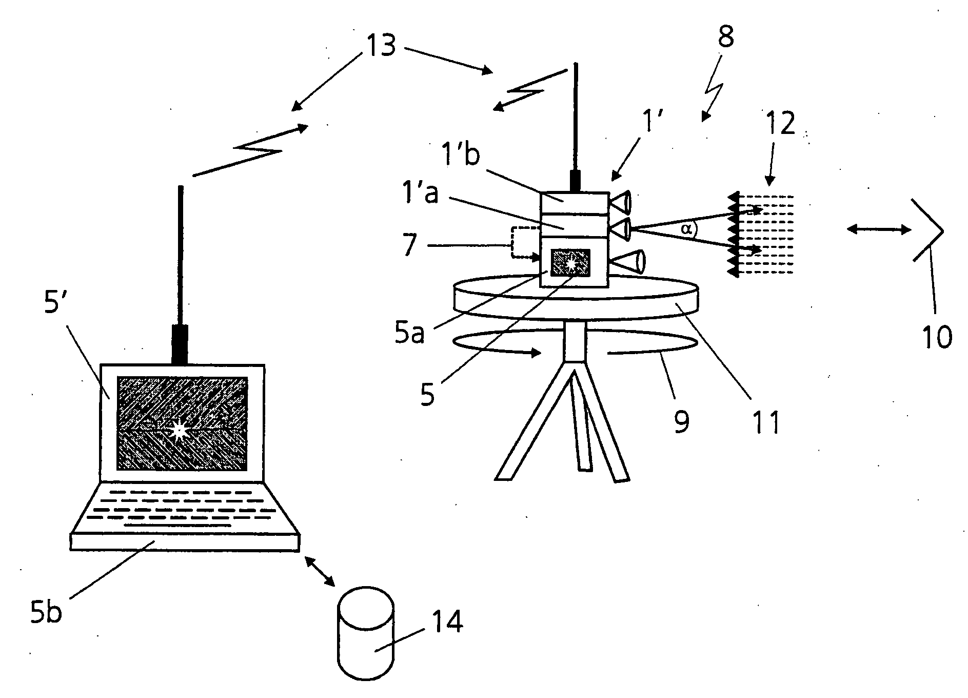
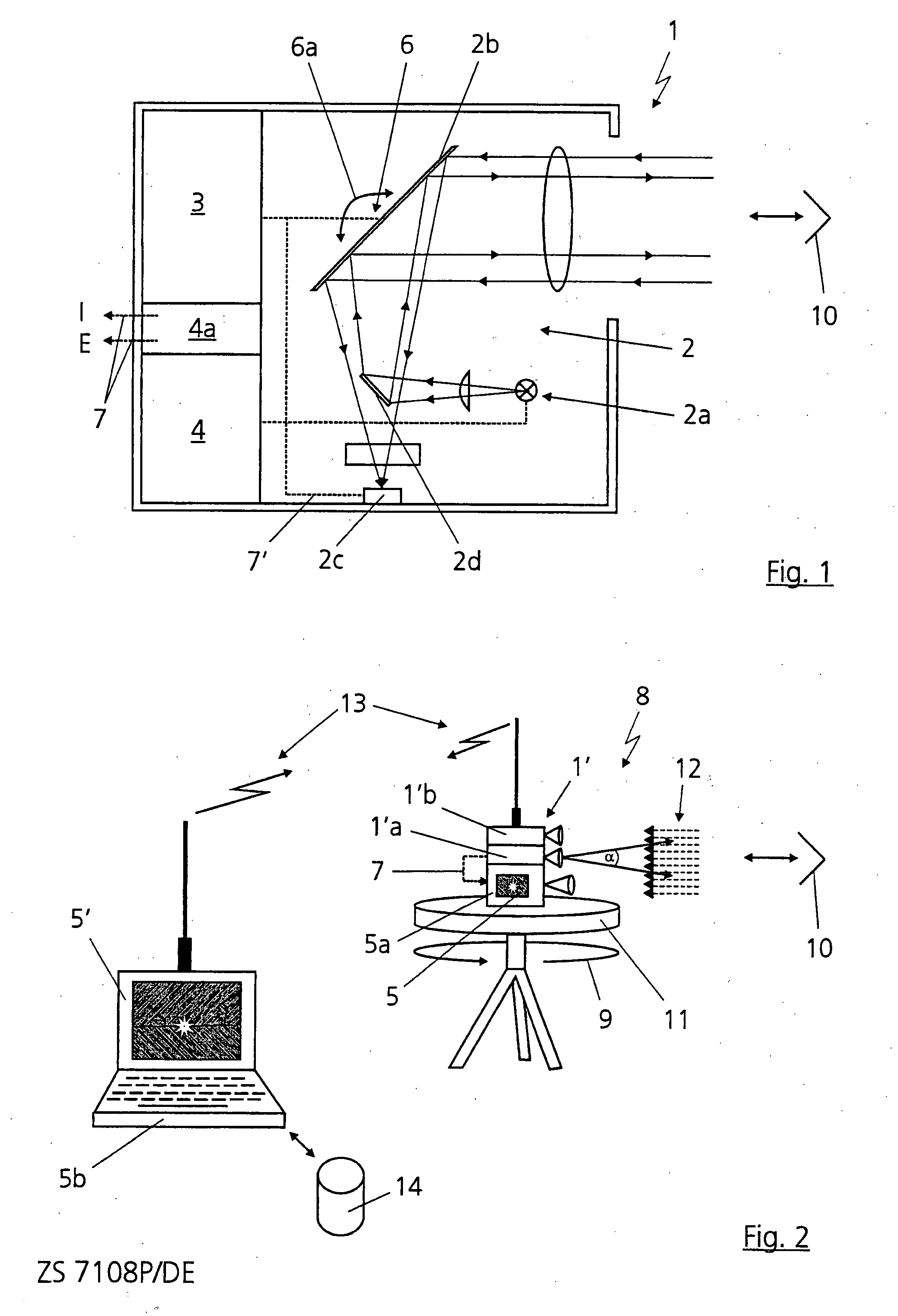
[0024]FIG. 1 shows an apparatus 1 according to the invention for detection of optical or optoelectronic objects or systems in a terrain area, which is not illustrated in any more detail.

[0025] The apparatus 1 is used as a scanning and / or identification device for detection of optical systems in the terrain area. For the purposes of the present application, the expression “optical system” means systems which can be located optically, for example enemy search or target systems, but in particular also including gunners, in particular snipers.

[0026] An optical system 10 or a sniper 10 is indicated in highly simplified form or symbolically as a triple mirror in FIGS. 1 and 2, with this system or gunner being located in the terrain area and being aimed at by the apparatus 1, 1′ according to the invention. In general terms, the reflecting element may be an optical system 10 with an (intermediate) image plane, on which a planar optical surface is arranged, which acts as a retroreflector. ...


PUM


Abstract

Abstract An apparatus for detection of optical systems in a terrain area, has at least: a laser arrangement with a laser light source, a moving mirror for scanning the terrain area and a photoelement for detection of retroreflected laser radiation from the laser light source, a scan position sensor for detection of a scanning direction, and a controller for determination of the position of an optical system to be detected, from a measurement which is carried out by means of the laser arrangement by evaluation of the intensity of retroreflected laser radiation from an optical surface of the optical system, and evaluation of the associated scanning direction detected by the scan position sensor, with the controller having an electronic interface via which information relating at least to the intensity and the elevation of the detected retroreflected laser radiation can be transmitted to at least one display apparatus.

Description

FIELD OF THE INVENTION [0001] The invention relates to an apparatus and a method for detection of optical systems in a terrain area. BACKGROUND OF THE INVENTION [0002] Appliances for the detection of sharp shooter or snipers are known, which are based on the so-called cat's eye effect, with retroreflected light from the optical appliances or systems of the gunners being detected. If the optical system is a telescopic sight, the radiation is reflected, for example, from the reticle, in the same direction from which the illuminating radiation came. A laser beam at an appropriate wavelength is generally used for active illumination of the optics to be detected, for this purpose. Visual light is generally not used for illumination since, on the one hand, eye safety with laser light in the visual band is not ensured and, on the other hand, the visual light can itself be easily detected. Inter alia, optics such as telescopic sights, telescopes, periscopes or thermal imagers, can be record...

Claims


Application Information

Patent Timeline
IPC IPC(8): G01C3/08G01S17/04
CPCG01S7/4802G01S7/4811G01S7/4817G02B26/105G01S17/42G01S17/88G01S17/026G01S17/04
Inventor HAAN, HUBERTUSKUERBITZ, GUNTHERSCHMIDT, HERBERT
Owner CARL ZEISS OPTRONICS
Features
  • R&D
  • Intellectual Property
  • Life Sciences
  • Materials
  • Tech Scout
  • Unparalleled Data Quality
  • Higher Quality Content
  • 60% Fewer Hallucinations
Learn More