Reception of redundant and non-redundant frames

a frame and non-redundancy technology, applied in the field of communication networks, can solve the problems of unreliable information about the frame length, undetected errors, and inability to provide for an active detection of singular frames deprived of said data identifiers,

Active Publication Date: 2007-09-27
HITACHI ENERGY SWITZERLAND AG
View PDF9 Cites 55 Cited by
  • Summary
  • Abstract
  • Description
  • Claims
  • Application Information

AI Technical Summary

Benefits of technology

[0014] Accordingly, an exemplary redundancy method comprises one or more of the following advantageous features. a) A support of mixed redundant and singular data traffic, which allows attaching non-critical devices to only one of the two redundant lines without having the interface of a receiving device declare the other line as faulty. b) A use of a long sequence of identifiers, which eliminates the need to create a timer and keep track of time-outs for each single identifier. c) A use of contiguous identifiers, enabling two counter values per source to be updated and out-of-sequence frames to be detected without going through tables of received identifiers. d) An extendability of the redundancy scheme to cover other requirements such as Ethernet security issues as well.

Problems solved by technology

However, in particular in the area of substation automation, third-party devices and / or mobile devices such as engineering laptops are often connected to one of the two redundant lines only and do not have knowledge of the particular redundancy protocol used by the majority of devices in the network.
In addition, a general problem of Ethernet frames resides in the fact that in some cases, there is no reliable information about the frame length.
Therefore, truncating a frame could result in a correct checksum in some cases, leading to an undetected error.
The method discards duplicates (i.e. redundant frames) at a low level control section of the receiving device by means of a data identifier, but does not provide for an active detection of singular frames deprived of said data identifier.
The occurrence of singular data is treated as a scarce case of abnormal behavior, and the method inherently processes the singular data to the upper level application without even considering to identify the singular data at the low level control section of the receiving device.

Method used


Image

  • Reception of redundant and non-redundant frames
  • Reception of redundant and non-redundant frames
  • Reception of redundant and non-redundant frames

Examples


Embodiment Construction

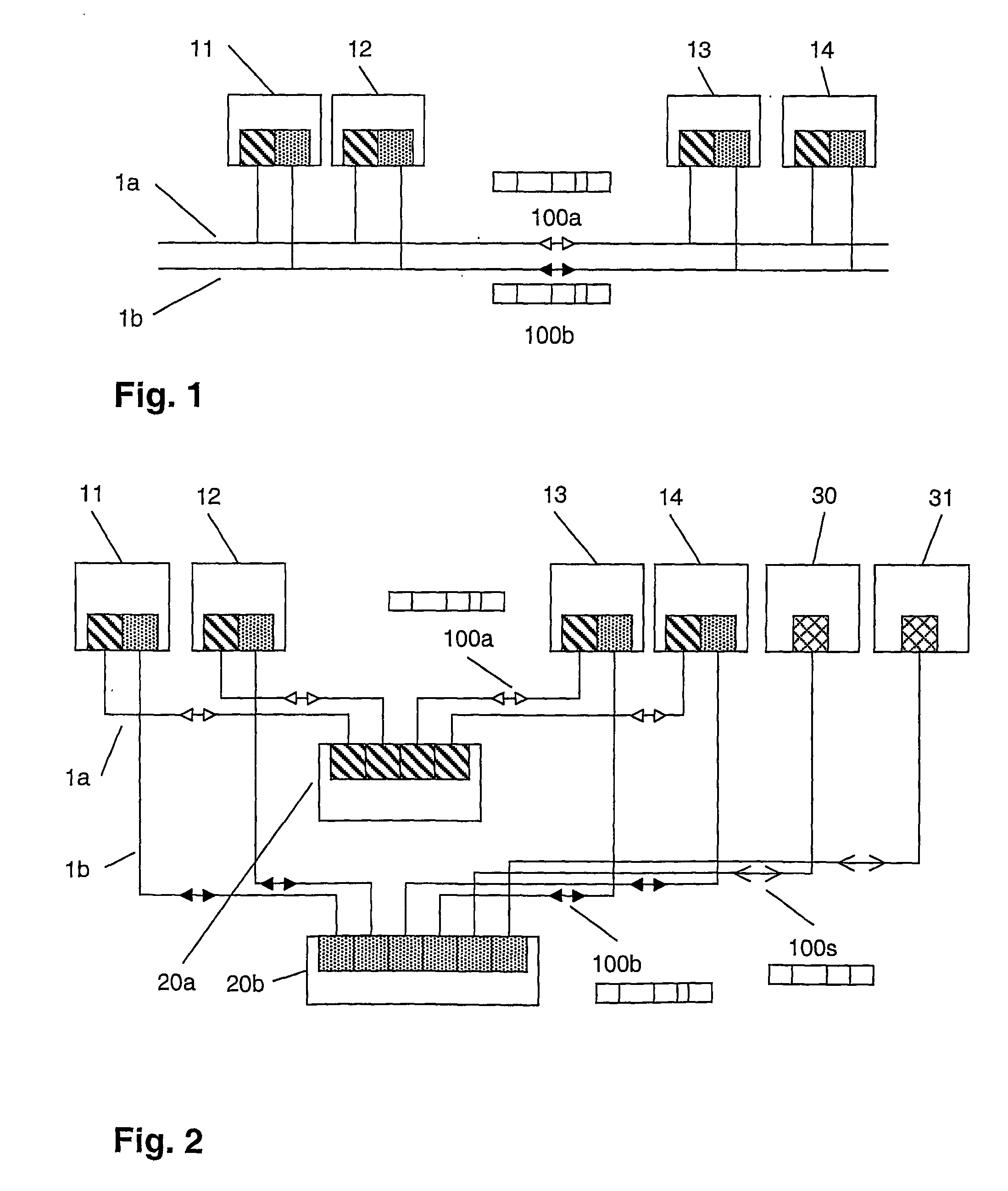
[0025]FIG. 1 shows a bus topology representing e.g. a field-bus according to IEC 61158 and FIG. 2 shows a switch topology of a communication network representing e.g. an Ethernet-type local area network (LAN). In both cases, two or more devices 11, 12, 13, 14 are connected by two lines 1a and 1b that are completely separated from each other to avoid a common source of failure. In the present context, the term line does not only describe a point-to-point physical link, but generally refers to one of two redundant paths that can be electrical, optical or based on another technology. As will be apparent from the following detailed description, the disclosure is independent of the number of connecting elements, hubs or switches and their respective arrangement, e.g. in a loop or tree topology, and is applicable to any type of network and communication media, as well as any number of redundant lines and even only partially, i.e. section-wise, redundant lines.

[0026] A sending device or s...


PUM


Abstract

The present disclosure relates to highly available communication networks, e.g., for industrial or utility applications such as substation automation. The devices are connected to two redundant lines through two independent transceivers and bus controllers, i.e. the physical layer and the link layer of the corresponding protocol stack is duplicated. For seamless operation, a sender sends frames simultaneously over both lines and a receiver accepts whichever frame of a pair comes first and ignores the late frame. An exemplary method is disclosed for discarding duplicate frames at the link layer without considering the higher protocol layers, based on a counter inserted in the frame and an algorithm for rejection, with a corresponding means to detect which frames operate according to the redundancy protocol.

Description

RELATED APPLICATIONS [0001] This application claims priority under 35 U.S.C. §119 to EP Application 04405708.1 filed in Europe on Nov. 16, 2004, and as a continuation application under 35 U.S.C. §120 to PCT / CH2005 / 000678 filed as an International Application on Nov. 15, 2005, designating the U.S., the entire contents of which are hereby incorporated by reference in their entireties.TECHNICAL FIELD [0002] The disclosure relates to the field of communication networks in applications such as vehicle control, drive control or substation automation. A method of receiving frames by a receiving device in a communication network is disclosed. BACKGROUND INFORMATION [0003] To increase the availability of data networks in vital or otherwise critical applications such as vehicle control, drive control or substation automation, redundancy is required. Basically, the latter may be provided by duplicating the communication lines, e.g. the electrical or optical transmission lines, as well as at le...

Claims


Application Information

Patent Timeline
Patent Type & Authority Applications(United States)
IPC IPC(8): H04J3/16H04L69/40
CPCH04L1/22H04L12/40189H04L12/413H04L69/40H04L2012/40273Y04S40/166H04L41/0659Y04S40/00
Inventor KIRRMANN, HUBERTDZUNG, DACFEY
Owner HITACHI ENERGY SWITZERLAND AG
Why Eureka
Try Eureka