Electro-optic device and electronic apparatus

a technology of optical devices and electronic equipment, applied in the direction of optical signal transducers, transducer details, instruments, etc., can solve the problems of large surface area for arranging sound generating members, insufficient downsizing demand, and inability to reduce the surface area around the display unit, so as to achieve the effect of sufficient downsizing of electronic equipmen

Inactive Publication Date: 2007-09-27
JAPAN DISPLAY WEST
View PDF9 Cites 53 Cited by
  • Summary
  • Abstract
  • Description
  • Claims
  • Application Information

AI Technical Summary

Benefits of technology

[0008]An advantage of some aspects of the invention is an electro-optic device in which the surface area around a display unit required for

Problems solved by technology

Therefore, the surface area around the display unit cannot be reduced, and hence a demand for downsizing is not sufficiently satisfied.
In particular, the electronic apparatus provided with a plurality of sound generating members has a problem that a large surface area for arranging the sound generating members is required.
However, when the size of the sound generating member is reduced, the volume that the sound generating member generates may be insufficient, and hence the volume is reduced.
Therefore, the demand for downsizing is not sufficiently satisfied.
However, when the size of the sound releasing hole is reduced, the sound generated by the sp

Method used


Image

  • Electro-optic device and electronic apparatus
  • Electro-optic device and electronic apparatus
  • Electro-optic device and electronic apparatus

Examples


second embodiment

of Electro-Optic Device

[0112]FIGS. 3A to 3C are explanatory drawings showing another example of the electro-optic device according to an aspect of the invention. FIG. 3A illustrates a structure in plan view, FIG. 3B is a cross-sectional view of FIG. 3A taken along the line IIIB-IIIB and FIG. 3C is a cross-sectional view of FIG. 3A taken along the line IIIC-IIIC. In the electro-optic device shown in FIGS. 3A to 3C, same parts as in the electro-optic device shown in FIGS. 1A to 1C are represented by same reference numerals and the description will not be made again.

[0113]As shown in FIG. 3A, an electro-optic device 1B in this embodiment has the display area 6a of the liquid crystal display device 2 which has a rectangular shape whose difference of length between the long side and the short side is smaller than the electro-optic device 1A shown in FIGS. 1A to 1C. As shown in FIGS. 3A and 3I, the speakers 3a and 3b are arranged so as to overlap with each other in plan view. The speakers...

third embodiment

of Electro-Optic Device

[0125]FIGS. 4A to 4D are explanatory drawings showing another example of the electro-optic device according to an aspect of the invention. FIG. 4A illustrates a structure in plan view, FIG. 4B is a cross-sectional view of FIG. 4A taken along the line IVB-IVB, FIG. 4C is a cross-sectional view of FIG. 4A taken along the line IVC-IVC, and FIG. 4D is a cross-sectional view of FIG. 4A taken along the line IVD-IVD. In the electro-optic device shown in FIGS. 4A to 4D, same parts as in the electro-optic device 1A shown in FIGS. 1A to 1C are represented by same reference numerals and the description will not be made again.

[0126]As shown in FIG. 4A, an electro-optic device 1C in this embodiment has the display area 6a of the liquid crystal display device 2 which has a rectangular shape whose difference in length between the long side 6e and the short sides 6b and 6c is smaller than the electro-optic device 1A shown in FIGS. 1A to 1C, whose difference in length between ...

fourth embodiment

of Electro-Optic Device

[0132]Referring now to the drawings, another embodiment of the invention will be described. In the drawings used in the description shown below, contraction scale is differentiated for the respective layers and the respective members in order to present the respective layers and the respective members in recognizable scales in the drawings.

[0133]FIGS. 7A to 7D are explanatory drawings showing an example of the electro-optic device according to an aspect of the invention. FIG. 7A illustrates a structure in plan view, FIG. 7B is a cross-sectional view of FIG. 7A taken along a line VIIB-VIIB, FIG. 7C is a cross-sectional view of FIG. 7A taken along a line VIIC-VIIC, and FIG. 7D is an enlarged drawing showing a part of the electro-optic device in an enlarged scale.

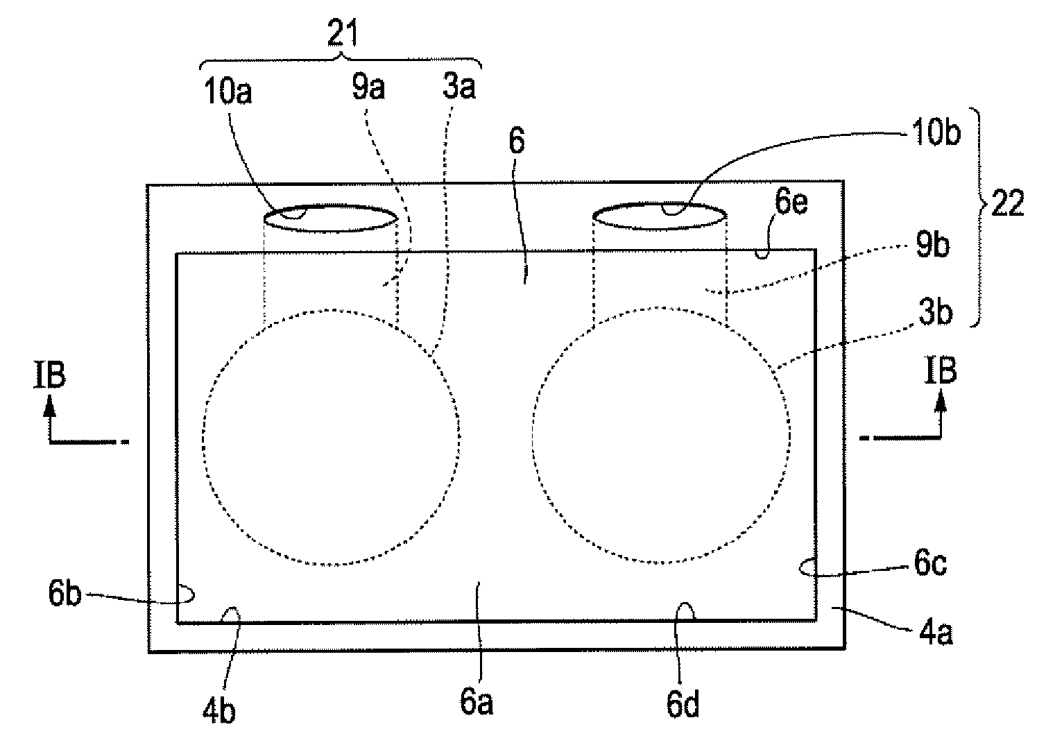
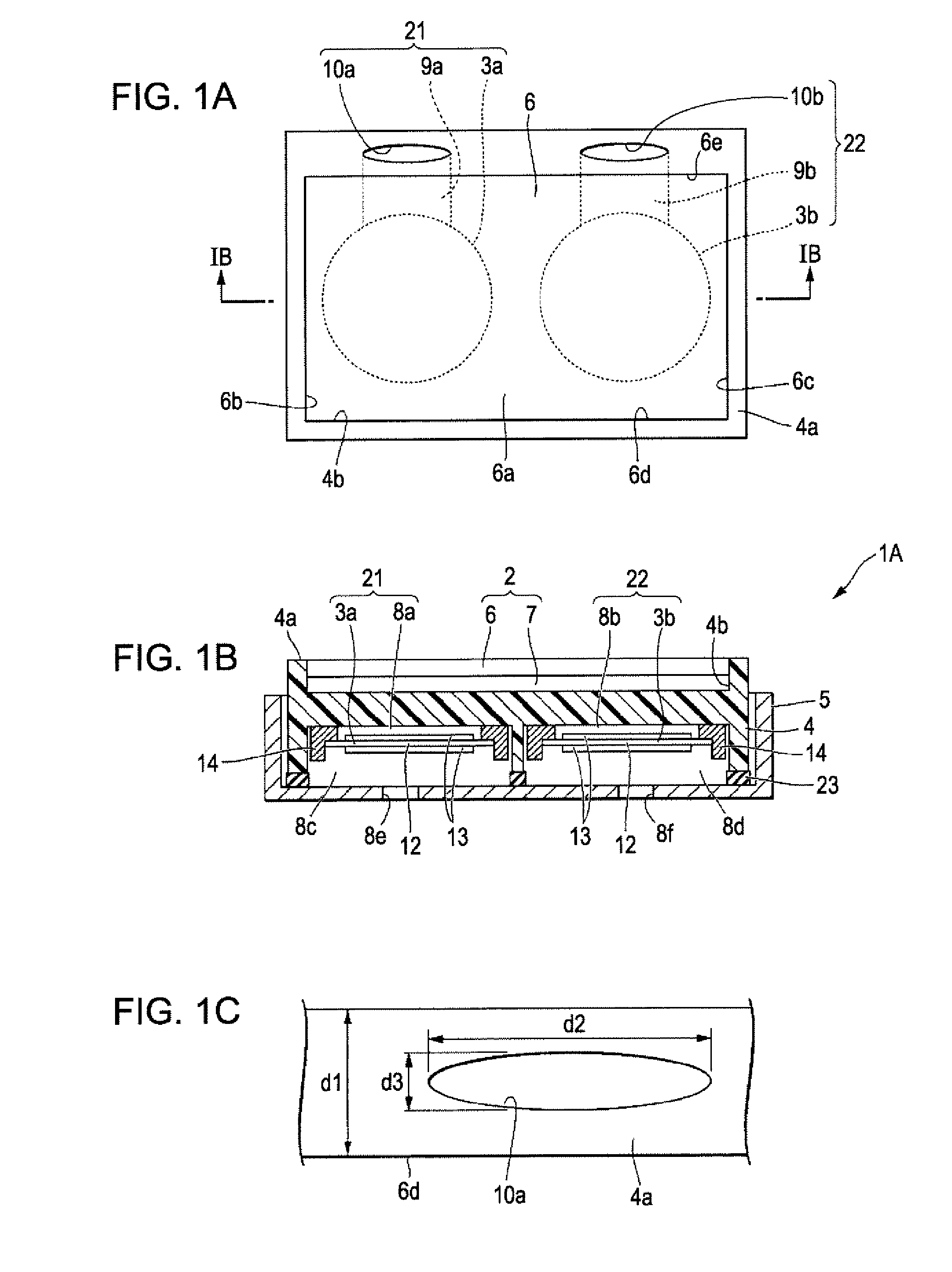
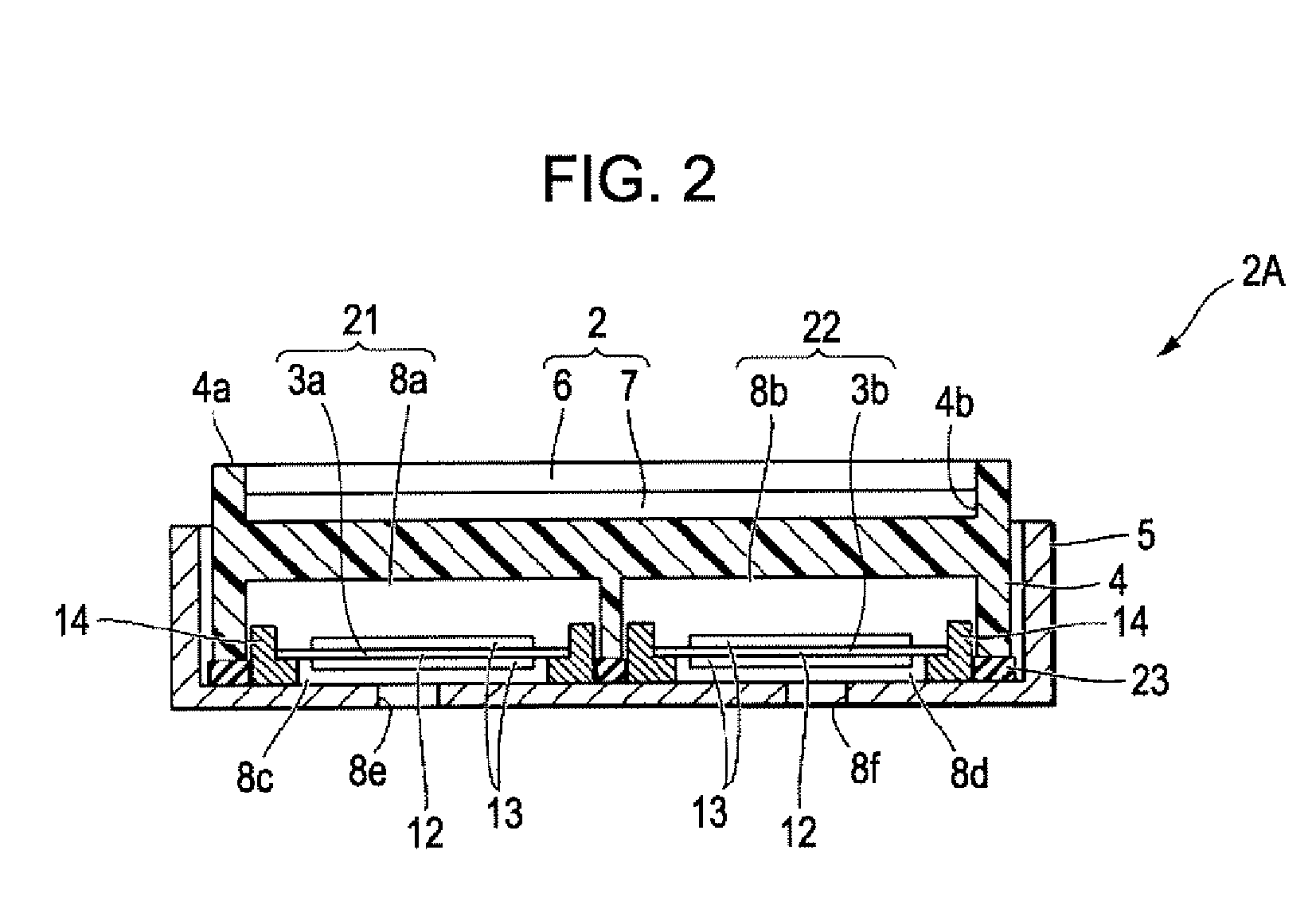
[0134]The electro-optic device 1A shown in FIGS. 7A to 7C includes a liquid crystal display device (display unit) 2, a sound generating member including a first sound generating members (first group) 21 ...


PUM


Abstract

An electro-optic device includes a display unit having a display area and a plurality of sound generating members, the plurality of sound generating members each include a speaker which is arranged so as to overlap the display area in plan view, and a sound releasing hole that outputs sounds generated by the speaker toward the outside, wherein the plurality of sound releasing holes which constitutes the plurality of sound generating members are arranged on the outside of the display area in plan view along part of the sides of the display area.

Description

BACKGROUND[0001]1. Technical Field[0002]The present invention relates to an electro-optic device having a display unit and a plurality of sound generating members, and an electronic apparatus provided with the electro-optic device.[0003]2. Related Art[0004]In recent years, electro-optic devices such as liquid crystal display device are widely provided as a display device for displaying various types of information relating to electronic apparatus as an image in an electronic apparatus such as mobile phones or mobile information terminal. The electro-optic device is a device that controls the state of optical output by electrical input, and examples include liquid crystal display devices, EL (Electra Luminescence) devices, and plasma display devices.[0005]The electronic apparatus also includes means that generates sounds. For example, in the case of the mobile phone, it is necessary to express the content of what a person on the other side of the phone talks with a voice, and hence a...

Claims


Application Information

Patent Timeline
IPC IPC(8): H04R25/00G02F1/1333
CPCH04R2499/11H04R23/008
Inventor WADA, HIROSHI
Owner JAPAN DISPLAY WEST
Why Eureka
Try Eureka